- 5.1. Using multiple channels
- 5.2. Sharing a transport between multiple channels in a JVM
- 5.3. Transport protocols
- 5.4. The concurrent stack
- 5.4.1. Overview
- 5.4.2. Elimination of up and down threads
- 5.4.3. Concurrent message delivery
- 5.4.4. Scopes: concurrent message delivery for messages from the same sender
- 5.4.5. Out-of-band messages
- 5.4.6. Replacing the default and OOB thread pools
- 5.4.7. Sharing of thread pools between channels in the same JVM
- 5.5. Using a custom socket factory
- 5.6. Handling network partitions
- 5.7. Flushing: making sure every node in the cluster received a message
- 5.8. Large clusters
- 5.9. STOMP support
- 5.10. Bridging between remote clusters
- 5.11. Relaying between multiple sites (RELAY2)
- 5.12. Daisychaining
- 5.13. Tagging messages with flags
- 5.14. Performance tests
- 5.15. Ergonomics
- 5.16. Supervising a running stack
- 5.17. Probe
This chapter discusses some of the more advanced concepts of JGroups with respect to using it and setting it up correctly.
When using a fully virtual synchronous protocol stack, the performance may not be great because of the larger number of protocols present. For certain applications, however, throughput is more important than ordering, e.g. for video/audio streams or airplane tracking. In the latter case, it is important that airplanes are handed over between control domains correctly, but if there are a (small) number of radar tracking messages (which determine the exact location of the plane) missing, it is not a problem. The first type of messages do not occur very often (typically a number of messages per hour), whereas the second type of messages would be sent at a rate of 10-30 messages/second. The same applies for a distributed whiteboard: messages that represent a video or audio stream have to be delivered as quick as possible, whereas messages that represent figures drawn on the whiteboard, or new participants joining the whiteboard have to be delivered according to a certain order.
The requirements for such applications can be solved by using two separate channels: one for control messages such as group membership, floor control etc and the other one for data messages such as video/audio streams (actually one might consider using one channel for audio and one for video). The control channel might use virtual synchrony, which is relatively slow, but enforces ordering and retransmission, and the data channel might use a simple UDP channel, possibly including a fragmentation layer, but no retransmission layer (losing packets is preferred to costly retransmission).
A transport protocol (UDP, TCP) has all the resources of a stack: the default thread pool, the OOB thread pool and the timer thread pool. If we run multiple channels in the same JVM, instead of creating 4 separate stacks with a separate transport each, we can create the transport protocol as a singleton protocol, shared by all 4 stacks.
If those transports happen to be the same (all 4 channels use UDP, for example), then we can share them and only create 1 instance of UDP. That transport instance is created and started only once; when the first channel is created, and is deleted when the last channel is closed.
If we have 4 channels inside of a JVM (as is the case in an application server such as JBoss), then we have 12 separate thread pools (3 per transport, 4 transports). Sharing the transport reduces this to 3.
Each channel created over a shared transport has to join a different cluster. An exception will be thrown if a channel sharing a transport tries to connect to a cluster to which another channel over the same transport is already connected.
This is needed to multiplex and de-multiplex messages between the shared transport and the different stacks running over it; when we have 3 channels (C1 connected to "cluster-1", C2 connected to "cluster-2" and C3 connected to "cluster-3") sending messages over the same shared transport, the cluster name with which the channel connected is used to multiplex messages over the shared transport: a header with the cluster name ("cluster-1") is added when C1 sends a message.
When a message with a header of "cluster-1" is received by the shared transport, it is used to demultiplex the message and dispatch it to the right channel (C1 in this example) for processing.
How channels can share a single transport is shown in Figure 5.1, “A shared transport”.
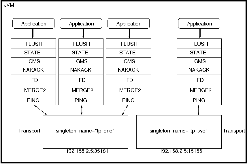
Here we see 4 channels which share 2 transports. Note that first 3 channels which share transport "tp_one" have the same protocols on top of the shared transport. This is not required; the protocols above "tp_one" could be different for each of the 3 channels as long as all applications residing on the same shared transport have the same requirements for the transport's configuration.
The "tp_two" transport is used by the application on the right side.
Note that the physical address of a shared channel is the same for all connected channels, so all applications sharing the first transport have physical address 192.168.2.5:35181.
To use shared transports, all we need to do is to add a property "singleton_name" to the transport configuration. All channels with the same singleton name will be shared:
<UDP ...

    singleton_name="tp_one" ...

/>
All channels using this configuration will now shared transport "tp_one". The channel on the right will have a different configuration, with singleton_name="tp_two".
A transport protocol refers to the protocol at the bottom of the protocol stack which is responsible for sending messages to and receiving messages from the network. There are a number of transport protocols in JGroups. They are discussed in the following sections.
A typical protocol stack configuration using UDP is:
<config xmlns="urn:org:jgroups"

        xmlns:xsi="http://www.w3.org/2001/XMLSchema-instance"

        xsi:schemaLocation="urn:org:jgroups http://www.jgroups.org/schema/JGroups-3.0.xsd">

    <UDP

         mcast_port="${jgroups.udp.mcast_port:45588}"

         tos="8"

         ucast_recv_buf_size="20M"

         ucast_send_buf_size="640K"

         mcast_recv_buf_size="25M"

         mcast_send_buf_size="640K"

         loopback="true"

         discard_incompatible_packets="true"

         max_bundle_size="64K"

         max_bundle_timeout="30"

         ip_ttl="${jgroups.udp.ip_ttl:2}"

         enable_bundling="true"

         enable_diagnostics="true"

         thread_naming_pattern="cl"


         timer_type="new"

         timer.min_threads="4"

         timer.max_threads="10"

         timer.keep_alive_time="3000"

         timer.queue_max_size="500"


         thread_pool.enabled="true"

         thread_pool.min_threads="2"

         thread_pool.max_threads="8"

         thread_pool.keep_alive_time="5000"

         thread_pool.queue_enabled="true"

         thread_pool.queue_max_size="10000"

         thread_pool.rejection_policy="discard"


         oob_thread_pool.enabled="true"

         oob_thread_pool.min_threads="1"

         oob_thread_pool.max_threads="8"

         oob_thread_pool.keep_alive_time="5000"

         oob_thread_pool.queue_enabled="false"

         oob_thread_pool.queue_max_size="100"

         oob_thread_pool.rejection_policy="Run"/>


    <PING timeout="2000"

            num_initial_members="3"/>

    <MERGE2 max_interval="30000"

            min_interval="10000"/>

    <FD_SOCK/>

    <FD_ALL/>

    <VERIFY_SUSPECT timeout="1500"  />

    <BARRIER />

    <pbcast.NAKACK use_mcast_xmit="true"

                   retransmit_timeout="300,600,1200"

                   discard_delivered_msgs="true"/>

    <UNICAST timeout="300,600,1200"/>

    <pbcast.STABLE stability_delay="1000" desired_avg_gossip="50000"

                   max_bytes="4M"/>

    <pbcast.GMS print_local_addr="true" join_timeout="3000"

                view_bundling="true"/>

    <UFC max_credits="2M"

         min_threshold="0.4"/>

    <MFC max_credits="2M"

         min_threshold="0.4"/>

    <FRAG2 frag_size="60K"  />

    <pbcast.STATE_TRANSFER />

</config>
In a nutshell the properties of the protocols are:
- UDP
This is the transport protocol. It uses IP multicasting to send messages to the entire cluster, or individual nodes. Other transports include TCP and TUNNEL.
- PING
This is the discovery protocol. It uses IP multicast (by default) to find initial members. Once found, the current coordinator can be determined and a unicast JOIN request will be sent to it in order to join the cluster.
- MERGE2
Will merge sub-clusters back into one cluster, kicks in after a network partition healed.
- FD_SOCK
Failure detection based on sockets (in a ring form between members). Generates notification if a member fails
- FD / FD_ALL
Failure detection based on heartbeat are-you-alive messages. Generates notification if a member fails
- VERIFY_SUSPECT
Double-checks whether a suspected member is really dead, otherwise the suspicion generated from protocol below is discarded
- BARRIER
Needed to transfer state; this will block messages that modify the shared state until a digest has been taken, then unblocks all threads. Not needed if no state transfer protocol is present.
- pbcast.NAKACK
Ensures (a) message reliability and (b) FIFO. Message reliability guarantees that a message will be received. If not, the receiver(s) will request retransmission. FIFO guarantees that all messages from sender P will be received in the order P sent them
- UNICAST
Same as NAKACK for unicast messages: messages from sender P will not be lost (retransmission if necessary) and will be in FIFO order (conceptually the same as TCP in TCP/IP)
- pbcast.STABLE
Deletes messages that have been seen by all members (distributed message garbage collection)
- pbcast.GMS
Membership protocol. Responsible for joining/leaving members and installing new views.
- UFC
Unicast Flow Control. Provides flow control between 2 members.
- MFC
Multicast Flow Control. Provides flow control between a sender and all cluster members.
- FRAG2
Fragments large messages into smaller ones and reassembles them back at the receiver side. For both multicast and unicast messages
- STATE_TRANSFER
Ensures that state is correctly transferred from an existing member (usually the coordinator) to a new member.
Message bundling is beneficial when sending many small messages; it queues them until they have accumulated a certain size, or until a timeout has elapsed. Then, the queued messages are assembled into a larger message, and that message is then sent. At the receiver, the large message is disassembled and the smaller messages are sent up the stack.
When sending many smaller messages, the ratio between payload and message headers might be small; say we send a "hello" string: the payload here is 7 bytes, whereas the addresses and headers (depending on the stack configuration) might be 30 bytes. However, if we bundle (say) 100 messages, then the payload of the large message is 700 bytes, but the header is still 30 bytes. Thus, we're able to send more actual data across the wire with one large message than many smaller ones.
Message bundling is conceptually similar to TCP's Nagling algorithm.
A sample configuration is shown below:
<UDP

    enable_bundling="true"

    max_bundle_size="64K"

    max_bundle_timeout="30"

/>
Here, bundling is enabled (the default). The max accumulated size is 64'000 bytes and we wait for 30 ms max. If at time T0, we're sending 10 smaller messages with an accumulated size of 2'000 bytes, but then send no more messages, then the timeout will kick in after 30 ms and the messages will get packed into a large message M and M will be sent. If we send 1000 messages of 100 bytes each, then - after exceeding 64'000 bytes (after ca. 64 messages) - we'll send the large message, and this might have taken only 3 ms.
While message bundling is good when sending many small messages asynchronously, it can be bad when invoking synchronous RPCs: say we're invoking 10 synchronous (blocking) RPCs across the cluster with an RpcDispatcher (see Section 4.2, “RpcDispatcher”), and the payload of the marshalled arguments of one call is less than 64K.
Because the RPC is blocking, we'll wait until the call has returned before invoking the next RPC.
For each RPC, the request takes up to 30 ms, and each response will also take up to 30 ms, for a total of 60 ms per call. So the 10 blocking RPCs would take a total of 600 ms !
This is clearly not desirable. However, there's a simple solution: we can use message flags (see Section 5.13, “Tagging messages with flags”) to override the default bundling behavior in the transport:
RpcDispatcher disp;

RequestOptions opts=new RequestOptions(ResponseMode.GET_ALL, 5000)

                        .setFlags(Message.DONT_BUNDLE);

RspList rsp_list=disp.callRemoteMethods(null,

                                        "print",

                                        new Object[]{i},

                                        new Class[]{int.class},

                                        opts);
The RequestOptions.setFlags(Message.DONT_BUNDLE) call tags the message
with the DONT_BUNDLE flag. When the message is to be sent by the transport, it will be sent
immediately, regardless of whether bundling is enabled in the transport.
Using the DONT_BUNDLE flag to invoke print() will take a few milliseconds
for 10 blocking RPCs versus 600 ms without the flag.
An alternative to setting the DONT_BUNDLE flag is to use futures to invoke 10 blocking RPCs:
List<Future<RspList>> futures=new ArrayList<Future<RspList>>();

for(int i=0; i < 10; i++) {

    Future<RspList> future=disp.callRemoteMethodsWithFuture(...);

    futures.add(future);

}


for(Future<RspList> future: futures) {

    RspList rsp_list=future.get();

    // do something with the response

}
Here we use callRemoteMethodsWithFuture() which (although the call
is blocking!) returns immediately, with a future. After invoking the 10 calls, we then grab the
results by fetching them from the futures.
Compared to the few milliseconds above, this will take ca 60 ms (30 for the request and 30 for
the responses), but this is still better than the 600 ms we get when not using the DONT_BUNDLE
flag. Note that, if the accumulated size of the 10 requests exceeds max_bundle_size,
the large message would be sent immediately, so this might even be faster than 30 ms for the request.
UDP uses IP multicast for sending messages to all members of a cluster, and UDP datagrams for unicast messages (sent to a single member). When started, it opens a unicast and multicast socket: the unicast socket is used to send/receive unicast messages, while the multicast socket sends/receives multicast messages. The physical address of the channel will be the address and port number of the unicast socket.
A protocol stack with UDP as transport protocol is typically used with clusters whose members run on the same host or are distributed across a LAN. Note that before running instances in different subnets, an admin has to make sure that IP multicast is enabled across subnets. It is often the case that IP multicast is not enabled across subnets. Refer to section Section 2.8, “It doesn't work !” for running a test program that determines whether members can reach each other via IP multicast. If this does not work, the protocol stack cannot use UDP with IP multicast as transport. In this case, the stack has to either use UDP without IP multicasting, or use a different transport such as TCP.
The protocol stack with UDP and PING as the bottom protocols use IP multicasting by default to send messages to all members (UDP) and for discovery of the initial members (PING). However, if multicasting cannot be used, the UDP and PING protocols can be configured to send multiple unicast messages instead of one multicast message [5].
To configure UDP to use multiple unicast messages to send a group message instead of using IP
multicasting, the ip_mcast property has to be set to false.
If we disable ip_mcast, we now also have to change the discovery protocol (PING). Because PING requires IP multicasting to be enabled in the transport, we cannot use it. Some of the alternatives are TCPPING (static list of member addresses), TCPGOSSIP (external lookup service), FILE_PING (shared directory), BPING (using broadcasts) or JDBC_PING (using a shared database).
See Section 7.3, “Initial membership discovery” for details on configuration of different discovery protocols.
TCP is a replacement for UDP as transport in cases where IP multicast cannot be used. This may be the case when operating over a WAN, where routers might discard IP multicast packets. Usually, UDP is used as transport in LANs, while TCP is used for clusters spanning WANs.
The properties for a typical stack based on TCP might look like this (edited for brevity):
<TCP bind_port="7800" />

<TCPPING timeout="3000"

         initial_hosts="${jgroups.tcpping.initial_hosts:HostA[7800],HostB[7801]}"

         port_range="1"

         num_initial_members="3"/>

<VERIFY_SUSPECT timeout="1500"  />

<pbcast.NAKACK use_mcast_xmit="false"

               retransmit_timeout="300,600,1200,2400,4800"

               discard_delivered_msgs="true"/>

<pbcast.STABLE stability_delay="1000" desired_avg_gossip="50000"

               max_bytes="400000"/>

<pbcast.GMS print_local_addr="true" join_timeout="3000"

               view_bundling="true"/>
- TCP
The transport protocol, uses TCP (from TCP/IP) to send unicast and multicast messages. In the latter case, it sends multiple unicast messages.
- TCPPING
Discovers the initial membership to determine coordinator. Join request will then be sent to coordinator.
- VERIFY_SUSPECT
Double checks that a suspected member is really dead
- pbcast.NAKACK
Reliable and FIFO message delivery
- pbcast.STABLE
Distributed garbage collection of messages seen by all members
- pbcast.GMS
Membership services. Takes care of joining and removing new/old members, emits view changes
When using TCP, each message to all of the cluster members is sent as multiple unicast messages (one to each member). Due to the fact that IP multicasting cannot be used to discover the initial members, another mechanism has to be used to find the initial membership. There are a number of alternatives (see Section 7.3, “Initial membership discovery” for a discussion of all discovery protocols):
TCPPING: uses a list of well-known group members that it solicits for initial membership
TCPGOSSIP: this requires a GossipRouter (see below), which is an external process, acting as a lookup service. Cluster members register with under their cluster name, and new members query the GossipRouter for initial cluster membership information.
The next two section illustrate the use of TCP with both TCPPING and TCPGOSSIP.
A protocol stack using TCP and TCPPING looks like this (other protocols omitted):
<TCP bind_port="7800" /> +

<TCPPING initial_hosts="HostA[7800],HostB[7800]" port_range="2"

         timeout="3000" num_initial_members="3" />
The concept behind TCPPING is that some selected cluster members assume the role of well-known hosts
from which the initial membership information can be retrieved. In the example,
HostA and HostB are designated members that will be
used by TCPPING to lookup the initial membership. The property bind_port
in TCP means that each member should try to assign port 7800 for itself.
If this is not possible it will try the next higher port (7801) and so on, until
it finds an unused port.
TCPPING will try to contact both HostA and
HostB, starting at port 7800 and ending at port
7800 + port_range, in the above example ports 7800 -
7802. Assuming that at least one of HostA or
HostB is up, a response will be received. To be absolutely sure to receive
a response, it is recommended to add all the hosts on which members of the cluster will be running
to the configuration.
TCPGOSSIP uses one or more GossipRouters to (1) register itself and (2)
fetch information about already registered cluster members. A configuration looks like this:
<TCP />

<TCPGOSSIP initial_hosts="HostA[5555],HostB[5555]" num_initial_members="3" />
The initial_hosts property is a comma-delimited list of GossipRouters.
In the example there are two GossipRouters on HostA and HostB, at port 5555.
A member always registers with all GossipRouters listed, but fetches information from the first available GossipRouter. If a GossipRouter cannot be accessed, it will be marked as failed and removed from the list. A task is then started, which tries to periodically reconnect to the failed process. On reconnection, the failed GossipRouter is marked as OK, and re-inserted into the list.
The advantage of having multiple GossipRouters is that, as long as at least one is running, new members will always be able to retrieve the initial membership.
Note that the GossipRouter should be started before any of the members.
Firewalls are usually placed at the connection to the internet. They shield local networks from outside attacks by screening incoming traffic and rejecting connection attempts to host inside the firewalls by outside machines. Most firewall systems allow hosts inside the firewall to connect to hosts outside it (outgoing traffic), however, incoming traffic is most often disabled entirely.
Tunnels are host protocols which encapsulate other protocols by multiplexing them at one end and demultiplexing them at the other end. Any protocol can be tunneled by a tunnel protocol.
The most restrictive setups of firewalls usually disable all incoming traffic, and only enable a few selected ports for outgoing traffic. In the solution below, it is assumed that one TCP port is enabled for outgoing connections to the GossipRouter.
JGroups has a mechanism that allows a programmer to tunnel a firewall. The solution involves a GossipRouter, which has to be outside of the firewall, so other members (possibly also behind firewalls) can access it.
The solution works as follows. A channel inside a firewall has to use protocol TUNNEL instead of UDP or TCP as transport. The recommended discovery protocol is PING. Here's a configuration:
<TUNNEL gossip_router_hosts="HostA[12001]" />

<PING />
TUNNEL uses a GossipRouter (outside the firewall) running on HostA at port
12001 for tunneling. Note that it is not recommended to use TCPGOSSIP for discovery if
TUNNEL is used (use PING instead). TUNNEL accepts one or multiple GossipRouters tor tunneling;
they can be listed as a comma delimited list of host[port] elements specified in property
gossip_router_hosts.
TUNNEL establishes a TCP connection to the GossipRouter
process (outside the firewall) that accepts messages from members and passes them on to other
members. This connection is initiated by the host inside the firewall and persists as long as the channel
is connected to a group. A GossipRouter will use the same connection
to send incoming messages to the channel that initiated the connection. This is perfectly legal, as TCP
connections are fully duplex. Note that, if GossipRouter tried to establish its own TCP connection to the
channel behind the firewall, it would fail. But it is okay to reuse the existing TCP connection,
established by the channel.
Note that TUNNEL has to be given the hostname and port of the GossipRouter process.
This example assumes a GossipRouter is running on HostA at port12001.
TUNNEL accepts one or multiple router hosts as a comma delimited list of host[port] elements specified in
property gossip_router_hosts.
Any time a message has to be sent, TUNNEL forwards the message to GossipRouter, which distributes it to its destination: if the message's destination field is null (send to all group members), then GossipRouter looks up the members that belong to that group and forwards the message to all of them via the TCP connections they established when connecting to GossipRouter. If the destination is a valid member address, then that member's TCP connection is looked up, and the message is forwarded to it [6] .
A GossipRouter is not a single point of failure. In a setup with multiple gossip routers, the routers do not communicate among themselves, and a single point of failure is avoided by having each channel simply connect to multiple available routers. In case one or more routers go down, the cluster members are still able to exchange messages through any of the remaining available router instances, if there are any.
For each send invocation, a channel goes through a list of available connections to routers and attempts to send the message on each connection until it succeeds. If a message can not be sent on any of the connections, an exception is raised. The default policy for connection selection is random. However, we provide an plug-in interface for other policies as well.
The GossipRouter configuration is static and is not updated for the lifetime of the channel. A list of available routers has to be provided in the channel's configuration file.
To tunnel a firewall using JGroups, the following steps have to be taken:
Check that a TCP port (e.g. 12001) is enabled in the firewall for outgoing traffic
Start the GossipRouter:
java org.jgroups.stack.GossipRouter -port 12001
Configure the TUNNEL protocol layer as instructed above.
Create a channel
The general setup is shown in Figure 5.2, “Tunneling a firewall” .
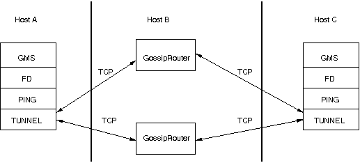
First, the GossipRouter process is created on host B. Note that host B should be outside the firewall,
and all channels in the same group should use the same GossipRouter process. When a channel on host A is
created, its TCPGOSSIP
protocol will register its address with the GossipRouter and retrieve the initial membership (assume this
is C). Now, a TCP connection with the GossipRouter is established by A; this will persist until A crashes
or voluntarily leaves the group. When A multicasts a message to the cluster, GossipRouter looks up all cluster
members (in this case, A and C) and forwards the message to all members, using their TCP connections. In
the example, A would receive its own copy of the multicast message it sent, and another copy would be sent
to C.
This scheme allows for example Java applets , which are only allowed to connect back to the host from which they were downloaded, to use JGroups: the HTTP server would be located on host B and the gossip and GossipRouter daemon would also run on that host. An applet downloaded to either A or C would be allowed to make a TCP connection to B. Also, applications behind a firewall would be able to talk to each other, joining a group.
However, there are several drawbacks: first, having to maintain a TCP connection for the duration of the connection might use up resources in the host system (e.g. in the GossipRouter), leading to scalability problems, second, this scheme is inappropriate when only a few channels are located behind firewalls, and the vast majority can indeed use IP multicast to communicate, and finally, it is not always possible to enable outgoing traffic on 2 ports in a firewall, e.g. when a user does not 'own' the firewall.
The concurrent stack (introduced in 2.5) provides a number of improvements over previous releases, which has some deficiencies:
- Large number of threads: each protocol had by default 2 threads, one for the up and one for the down queue. They could be disabled per protocol by setting up_thread or down_thread to false. In the new model, these threads have been removed.
- Sequential delivery of messages: JGroups used to have a single queue for incoming messages, processed by one thread. Therefore, messages from different senders were still processed in FIFO order. In 2.5 these messages can be processed in parallel.
- Out-of-band messages: when an application doesn't care about the ordering properties of a message, the OOB flag can be set and JGroups will deliver this particular message without regard for any ordering.
The architecture of the concurrent stack is shown in Figure 5.3, “The concurrent stack”. The changes were made entirely inside of the transport protocol (TP, with subclasses UDP, TCP and TCP_NIO). Therefore, to configure the concurrent stack, the user has to modify the config for (e.g.) UDP in the XML file.
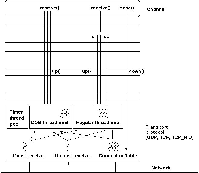
The concurrent stack consists of 2 thread pools (java.util.concurrent.Executor): the out-of-band (OOB) thread pool and the regular thread pool. Packets are received by multicast or unicast receiver threads (UDP) or a ConnectionTable (TCP, TCP_NIO). Packets marked as OOB (with Message.setFlag(Message.OOB)) are dispatched to the OOB thread pool, and all other packets are dispatched to the regular thread pool.
When a thread pool is disabled, then we use the thread of the caller (e.g. multicast or unicast receiver threads or the ConnectionTable) to send the message up the stack and into the application. Otherwise, the packet will be processed by a thread from the thread pool, which sends the message up the stack. When all current threads are busy, another thread might be created, up to the maximum number of threads defined. Alternatively, the packet might get queued up until a thread becomes available.
The point of using a thread pool is that the receiver threads should only receive the packets and forward them to the thread pools for processing, because unmarshalling and processing is slower than simply receiving the message and can benefit from parallelization.
Note that this is preliminary and names or properties might change
We are thinking of exposing the thread pools programmatically, meaning that a developer might be able to set both threads pools programmatically, e.g. using something like TP.setOOBThreadPool(Executor executor).
Here's an example of the new configuration:
<UDP

    thread_naming_pattern="cl"


    thread_pool.enabled="true"

    thread_pool.min_threads="1"

    thread_pool.max_threads="100"

    thread_pool.keep_alive_time="20000"

    thread_pool.queue_enabled="false"

    thread_pool.queue_max_size="10"

    thread_pool.rejection_policy="Run"


    oob_thread_pool.enabled="true"

    oob_thread_pool.min_threads="1"

    oob_thread_pool.max_threads="4"

    oob_thread_pool.keep_alive_time="30000"

    oob_thread_pool.queue_enabled="true"

    oob_thread_pool.queue_max_size="10"

    oob_thread_pool.rejection_policy="Run"/>
The attributes for the 2 thread pools are prefixed with thread_pool and oob_thread_pool respectively.
The attributes are listed below. The roughly correspond to the options of a java.util.concurrent.ThreadPoolExecutor in JDK 5.
Table 5.1. Attributes of thread pools
| Name | Description |
|---|---|
| thread_naming_pattern | Determines how threads are named that are running from thread pools in concurrent stack. Valid values include any combination of "cl" letters, where "c" includes the cluster name and "l" includes local address of the channel. The default is "cl" |
| enabled | Whether of not to use a thread pool. If set to false, the caller's thread is used. |
| min_threads | The minimum number of threads to use. |
| max_threads | The maximum number of threads to use. |
| keep_alive_time | Number of milliseconds until an idle thread is placed back into the pool |
| queue_enabled | Whether of not to use a (bounded) queue. If enabled, when all minimum threads are busy, work items are added to the queue. When the queue is full, additional threads are created, up to max_threads. When max_threads have been reached (and the queue is full), the rejection policy is consulted. |
| max_size | The maximum number of elements in the queue. Ignored if the queue is disabled |
| rejection_policy | Determines what happens when the thread pool (and queue, if enabled) is full. The default is to run on the caller's thread. "Abort" throws an runtime exception. "Discard" discards the message, "DiscardOldest" discards the oldest entry in the queue. Note that these values might change, for example a "Wait" value might get added in the future. |
By removing the 2 queues/protocol and the associated 2 threads, we effectively reduce the number of threads needed to handle a message, and thus context switching overhead. We also get clear and unambiguous semantics for Channel.send(): now, all messages are sent down the stack on the caller's thread and the send() call only returns once the message has been put on the network. In addition, an exception will only be propagated back to the caller if the message has not yet been placed in a retransmit buffer. Otherwise, JGroups simply logs the error message but keeps retransmitting the message. Therefore, if the caller gets an exception, the message should be re-sent.
On the receiving side, a message is handled by a thread pool, either the regular or OOB thread pool. Both thread pools can be completely eliminated, so that we can save even more threads and thus further reduce context switching. The point is that the developer is now able to control the threading behavior almost completely.
Up to version 2.5, all messages received were processed by a single thread, even if the messages were sent by different senders. For instance, if sender A sent messages 1,2 and 3, and B sent message 34 and 45, and if A's messages were all received first, then B's messages 34 and 35 could only be processed after messages 1-3 from A were processed !
Now, we can process messages from different senders in parallel, e.g. messages 1, 2 and 3 from A can be processed by one thread from the thread pool and messages 34 and 35 from B can be processed on a different thread.
As a result, we get a speedup of almost N for a cluster of N if every node is sending messages and we configure the thread pool to have at least N threads. There is actually a unit test (ConcurrentStackTest.java) which demonstrates this.
Deprecated in 3.3
In 3.3, SCOPE is replaced with the Section 4.3, “Asynchronous invocation in MessageDispatcher and RpcDispatcher”. SCOPE will probably be removed in 4.x.
In the previous paragraph, we showed how the concurrent stack delivers messages from different senders concurrently. But all (non-OOB) messages from the same sender P are delivered in the order in which P sent them. However, this is not good enough for certain types of applications.
Consider the case of an application which replicates HTTP sessions. If we have sessions X, Y and Z, then updates to these sessions are delivered in the order in which there were performed, e.g. X1, X2, X3, Y1, Z1, Z2, Z3, Y2, Y3, X4. This means that update Y1 has to wait until updates X1-3 have been delivered. If these updates take some time, e.g. spent in lock acquisition or deserialization, then all subsequent messages are delayed by the sum of the times taken by the messages ahead of them in the delivery order.
However, in most cases, updates to different web sessions should be completely unrelated, so they could be delivered concurrently. For instance, a modification to session X should not have any effect on session Y, therefore updates to X, Y and Z can be delivered concurrently.
One solution to this is out-of-band (OOB) messages (see next paragraph). However, OOB messages do not guarantee ordering, so updates X1-3 could be delivered as X1, X3, X2. If this is not wanted, but messages pertaining to a given web session should all be delivered concurrently between sessions, but ordered within a given session, then we can resort to scoped messages.
Scoped messages apply only to regular (non-OOB) messages, and are delivered concurrently between scopes, but ordered within a given scope. For example, if we used the sessions above (e.g. the jsessionid) as scopes, then the delivery could be as follows ('->' means sequential, '||' means concurrent):
X1 -> X2 -> X3 -> X4 || Y1 -> Y2 -> Y3 || Z1 -> Z2 -> Z3
This means that all updates to X are delivered in parallel to updates to Y and updates to Z. However, within a given scope, updates are delivered in the order in which they were performed, so X1 is delivered before X2, which is deliverd before X3 and so on.
Taking the above example, using scoped messages, update Y1 does not have to wait for updates X1-3 to complete, but is processed immediately.
To set the scope of a message, use method Message.setScope(short).
Scopes are implemented in a separate protocol called Section 7.14.4, “SCOPE”. This protocol has to be placed somewhere above ordering protocols like UNICAST or NAKACK (or SEQUENCER for that matter).
Uniqueness of scopes
Note that scopes should be as unique as possible. Compare this to hashing: the fewer collisions there are, the better the concurrency will be. So, if for example, two web sessions pick the same scope, then updates to those sessions will be delivered in the order in which they were sent, and not concurrently. While this doesn't cause erraneous behavior, it defies the purpose of SCOPE.
Also note that, if multicast and unicast messages have the same scope, they will be delivered in sequence. So if A multicasts messages to the group with scope 25, and A also unicasts messages to B with scope 25, then A's multicasts and unicasts will be delivered in order at B ! Again, this is correct, but since multicasts and unicasts are unrelated, might slow down things !
OOB messages completely ignore any ordering constraints the stack might have. Any message marked as OOB will be processed by the OOB thread pool. This is necessary in cases where we don't want the message processing to wait until all other messages from the same sender have been processed, e.g. in the heartbeat case: if sender P sends 5 messages and then a response to a heartbeat request received from some other node, then the time taken to process P's 5 messages might take longer than the heartbeat timeout, so that P might get falsely suspected ! However, if the heartbeat response is marked as OOB, then it will get processed by the OOB thread pool and therefore might be concurrent to its previously sent 5 messages and not trigger a false suspicion.
The 2 unit tests UNICAST_OOB_Test and NAKACK_OOB_Test demonstrate how OOB messages influence the ordering, for both unicast and multicast messages.
In 2.7, there are 3 thread pools and 4 thread factories in TP:
Table 5.2. Thread pools and factories in TP
| Name | Description |
|---|---|
| Default thread pool | This is the pool for handling incoming messages. It can be fetched using getDefaultThreadPool() and replaced using setDefaultThreadPool(). When setting a thread pool, the old thread pool (if any) will be shutdown and all of it tasks cancelled first |
| OOB thread pool | This is the pool for handling incoming OOB messages. Methods to get and set it are getOOBThreadPool() and setOOBThreadPool() |
| Timer thread pool | This is the thread pool for the timer. The max number of threads is set through the timer.num_threads property. The timer thread pool cannot be set, it can only be retrieved using getTimer(). However, the thread factory of the timer can be replaced (see below) |
| Default thread factory | This is the thread factory (org.jgroups.util.ThreadFactory) of the default thread pool, which handles incoming messages. A thread pool factory is used to name threads and possibly make them daemons. It can be accessed using getDefaultThreadPoolThreadFactory() and setDefaultThreadPoolThreadFactory() |
| OOB thread factory | This is the thread factory for the OOB thread pool. It can be retrieved using getOOBThreadPoolThreadFactory() and set using method setOOBThreadPoolThreadFactory() |
| Timer thread factory | This is the thread factory for the timer thread pool. It can be accessed using getTimerThreadFactory() and setTimerThreadFactory() |
| Global thread factory | The global thread factory can get used (e.g. by protocols) to create threads which don't live in the transport, e.g. the FD_SOCK server socket handler thread. Each protocol has a method getTransport(). Once the TP is obtained, getThreadFactory() can be called to get the global thread factory. The global thread factory can be replaced with setThreadFactory() |
Note
Note that thread pools and factories should be replaced after a channel has been created and
before it is connected (JChannel.connect()).
In 2.7, the default and OOB thread pools can be shared between instances running inside the same JVM. The advantage here is that multiple channels running within the same JVM can pool (and therefore save) threads. The disadvantage is that thread naming will not show to which channel instance an incoming thread belongs to.
Note that we can not just shared thread pools between JChannels within the same JVM, but we can also share entire transports. For details see Section 5.2, “Sharing a transport between multiple channels in a JVM”.
JGroups creates all of its sockets through a SocketFactory, which is located in the transport (TP) or TP.ProtocolAdapter (in a shared transport). The factory has methods to create sockets (Socket, ServerSocket, DatagramSocket and MulticastSocket) [7], closen sockets and list all open sockets. Every socket creation method has a service name, which could be for example "jgroups.fd_sock.srv_sock". The service name is used to look up a port (e.g. in a config file) and create the correct socket.
To provide one's own socket factory, the following has to be done: if we have a non-shared transport, the code below creates a SocketFactory implementation and sets it in the transport:
JChannel ch;

MySocketFactory factory; // e.g. extends DefaultSocketFactory

ch=new JChannel("config.xml");

ch.setSocketFactory(new MySocketFactory());

ch.connect("demo");
If a shared transport is used, then we have to set 2 socket factories: 1 in the shared transport and one in the TP.ProtocolAdapter:
JChannel c1=new JChannel("config.xml"), c2=new JChannel("config.xml");


TP transport=c1.getProtocolStack().getTransport();

transport.setSocketFactory(new MySocketFactory("transport"));


c1.setSocketFactory(new MySocketFactory("first-cluster"));

c2.setSocketFactory(new MySocketFactory("second-cluster"));


c1.connect("first-cluster");

c2.connect("second-cluster");
First, we grab one of the channels to fetch the transport and set a SocketFactory in it. Then we set one SocketFactory per channel that resides on the shared transport. When JChannel.connect() is called, the SocketFactory will be set in TP.ProtocolAdapter.
Network partitions can be caused by switch, router or network interface crashes, among other things. If we have a cluster {A,B,C,D,E} spread across 2 subnets {A,B,C} and {D,E} and the switch to which D and E are connected crashes, then we end up with a network partition, with subclusters {A,B,C} and {D,E}.
A, B and C can ping each other, but not D or E, and vice versa. We now have 2 coordinators, A and D. Both subclusters operate independently, for example, if we maintain a shared state, subcluster {A,B,C} replicate changes to A, B and C.
This means, that if during the partition, some clients access {A,B,C}, and others {D,E}, then we end up with different states in both subclusters. When a partition heals, the merge protocol (e.g. MERGE2) will notify A and D that there were 2 subclusters and merge them back into {A,B,C,D,E}, with A being the new coordinator and D ceasing to be coordinator.
The question is what happens with the 2 diverged substates ?
There are 2 solutions to merging substates: first we can attempt to create a new state from the 2 substates, and secondly we can shut down all members of the non primary partition, such that they have to re-join and possibly reacquire the state from a member in the primary partition.
In both cases, the application has to handle a MergeView (subclass of View), as shown in the code below:
public void viewAccepted(View view) {

    if(view instanceof MergeView) {

        MergeView tmp=(MergeView)view;

        Vector<View> subgroups=tmp.getSubgroups();

        // merge state or determine primary partition

        // run in a separate thread !

    }

}
It is essential that the merge view handling code run on a separate thread if it needs more than a few milliseconds, or else it would block the calling thread.
The MergeView contains a list of views, each view represents a subgroups and has the list of members which formed this group.
The application has to merge the substates from the various subgroups ({A,B,C} and {D,E}) back into one single state for {A,B,C,D,E}. This task has to be done by the application because JGroups knows nothing about the application state, other than it is a byte buffer.
If the in-memory state is backed by a database, then the solution is easy: simply discard the in-memory state and fetch it (eagerly or lazily) from the DB again. This of course assumes that the members of the 2 subgroups were able to write their changes to the DB. However, this is often not the case, as connectivity to the DB might have been severed by the network partition.
Another solution could involve tagging the state with time stamps. On merging, we could compare the time stamps for the substates and let the substate with the more recent time stamps win.
Yet another solution could increase a counter for a state each time the state has been modified. The state with the highest counter wins.
Again, the merging of state can only be done by the application. Whatever algorithm is picked to merge state, it has to be deterministic.
The primary partition approach is simple: on merging, one subgroup is designated as the primary partition and all others as non-primary partitions. The members in the primary partition don't do anything, whereas the members in the non-primary partitions need to drop their state and re-initialize their state from fresh state obtained from a member of the primary partition.
The code to find the primary partition needs to be deterministic, so that all members pick the same primary partition. This could be for example the first view in the MergeView, or we could sort all members of the new MergeView and pick the subgroup which contained the new coordinator (the one from the consolidated MergeView). Another possible solution could be to pick the largest subgroup, and, if there is a tie, sort the tied views lexicographically (all Addresses have a compareTo() method) and pick the subgroup with the lowest ranked member.
Here's code which picks as primary partition the first view in the MergeView, then re-acquires the state from the new coordinator of the combined view:
public static void main(String[] args) throws Exception {

    final JChannel ch=new JChannel("/home/bela/udp.xml");

    ch.setReceiver(new ExtendedReceiverAdapter() {

        public void viewAccepted(View new_view) {

            handleView(ch, new_view);

        }

    });

    ch.connect("x");

    while(ch.isConnected())

        Util.sleep(5000);

    }


    private static void handleView(JChannel ch, View new_view) {

        if(new_view instanceof MergeView) {

            ViewHandler handler=new ViewHandler(ch, (MergeView)new_view);

            // requires separate thread as we don't want to block JGroups

            handler.start();

        }

    }


    private static class ViewHandler extends Thread {

        JChannel ch;

        MergeView view;


        private ViewHandler(JChannel ch, MergeView view) {

            this.ch=ch;

            this.view=view;

        }


        public void run() {

            Vector<View> subgroups=view.getSubgroups();

            View tmp_view=subgroups.firstElement(); // picks the first

            Address local_addr=ch.getLocalAddress();

            if(!tmp_view.getMembers().contains(local_addr)) {

                System.out.println("Not member of the new primary partition ("

                                   + tmp_view + "), will re-acquire the state");

                try {

                    ch.getState(null, 30000);

                }

                catch(Exception ex) {

                }

            }

            else {

                System.out.println("Not member of the new primary partition ("

                                   + tmp_view + "), will do nothing");

            }

        }

}
The handleView() method is called from viewAccepted(), which is called whenever there is a new view. It spawns a new thread which gets the subgroups from the MergeView, and picks the first subgroup to be the primary partition. Then, if it was a member of the primary partition, it does nothing, and if not, it reaqcuires the state from the coordinator of the primary partition (A).
The downside to the primary partition approach is that work (= state changes) on the non-primary partition is discarded on merging. However, that's only problematic if the data was purely in-memory data, and not backed by persistent storage. If the latter's the case, use state merging discussed above.
It would be simpler to shut down the non-primary partition as soon as the network partition is detected, but that a non trivial problem, as we don't know whether {D,E} simply crashed, or whether they're still alive, but were partitioned away by the crash of a switch. This is called a split brain syndrome, and means that none of the members has enough information to determine whether it is in the primary or non-primary partition, by simply exchanging messages.
In certain situations, we can avoid having multiple subgroups where every subgroup is able to make progress, and on merging having to discard state of the non-primary partitions.
If we have a fixed membership, e.g. the cluster always consists of 5 nodes, then we can run code on a view reception that determines the primary partition. This code
- assumes that the primary partition has to have at least 3 nodes
- any cluster which has less than 3 nodes doesn't accept modfications. This could be done for shared state for example, by simply making the {D,E} partition read-only. Clients can access the {D,E} partition and read state, but not modify it.
- As an alternative, clusters without at least 3 members could shut down, so in this case D and E would leave the cluster.
The algorithm is shown in pseudo code below:
On initialization:
    - Mark the node as read-only

On view change V:
    - If V has >= N members:
        - If not read-write: get state from coord and switch to read-write
    - Else: switch to read-only
Of course, the above mechanism requires that at least 3 nodes are up at any given time, so upgrades have to be done in a staggered way, taking only one node down at a time. In the worst case, however, this mechanism leaves the cluster read-only and notifies a system admin, who can fix the issue. This is still better than shutting the entire cluster down.
To change this, we can turn on virtual synchrony (by adding FLUSH to the top of the stack), which guarantees that
- A message M sent in V1 will be delivered in V1. So, in the example above, M1 would get delivered in view V1; by A, B and C, but not by D.
- The set of messages seen by members in V1 is the same for all members before a new view V2 is installed. This is important, as it ensures that all members in a given view see the same messages. For example, in a group {A,B,C}, C sends 5 messages. A receives all 5 messages, but B doesn't. Now C crashes before it can retransmit the messages to B. FLUSH will now ensure, that before installing V2={A,B} (excluding C), B gets C's 5 messages. This is done through the flush protocol, which has all members reconcile their messages before a new view is installed. In this case, A will send C's 5 messages to B.
Sometimes it is important to know that every node in the cluster received all messages up to a certain point, even if there is no new view being installed. To do this (initiate a manual flush), an application programmer can call Channel.startFlush() to start a flush and Channel.stopFlush() to terminate it.
Channel.startFlush() flushes all pending messages out of the system. This stops all senders (calling Channel.down() during a flush will block until the flush has completed)[8]. When startFlush() returns, the caller knows that (a) no messages will get sent anymore until stopFlush() is called and (b) all members have received all messages sent before startFlush() was called.
Channel.stopFlush() terminates the flush protocol, no blocked senders can resume sending messages.
Note that the FLUSH protocol has to be present on top of the stack, or else the flush will fail.
This section is a collection of best practices and tips and tricks for running large clusters on JGroups.
By large clusters, we mean several hundred nodes in a cluster. These recommendations are captured in
udp-largecluster.xml which is shipped with JGroups.
Note
This is work-in-progress, and udp-largecluster.xml is likely to see changes
in the future.
When we have a chatty protocol, scaling to a large number of nodes might be a problem: too many messages are sent and - because they are generated in addition to the regular traffic - this can have a negative impact on the cluster. A possible impact is that more of the regular messages are dropped, and have to be retransmitted, which impacts performance. Or heartbeats are dropped, leading to false suspicions. So while the negative effects of chatty protocols may not be seen in small clusters, they will be seen in large clusters !
Failure detection protocols determine when a member is unresponsive, and subsequently suspect it. Usually (FD, FD_ALL), messages (heartbeats) are used to determine the health of a member, but we can also use TCP connections (FD_SOCK) to connect to a member P, and suspect P when the connection is closed.
Heartbeating requires messages to be sent around, and we need to be careful to limit the number of messages sent by a failure detection protocol (1) to detect crashed members and (2) when a member has been suspected. The following sections discuss how to configure FD_ALL, FD and FD_SOCK, the most commonly used failure detection protocols, for use in large clusters.
FD_SOCK is discussed in detail in Section 7.5.3, “FD_SOCK”.
FD uses a ring topology, where every member sends heartbeats to its neighbor only. We recommend to use this protocol only when TCP is the transport, as it generates a lot of traffic in large clusters.
For details see Section 7.5.1, “FD”.
FD_ALL has every member periodically multicast a heartbeat, and everyone updates internal
tables of members and their last heartbeat received. When a member hasn't received a heartbeat
from any given member for more than timeout ms, that member will get
suspected.
FD_ALL is the recommended failure detection protocol when the transport provides IP multicasting capabilities (UDP).
For details see Section 7.5.2, “FD_ALL”.
STOMP is a JGroups protocol which implements the STOMP protocol. Currently (as of Aug 2011), transactions and acks are not implemented.
Adding the STOMP protocol to a configuration means that
Clients written in different languages can subscribe to destinations, send messages to destinations, and receive messages posted to (subscribed) destinations. This is similar to JMS topics.
Clients don't need to join any cluster; this allows for light weight clients, and we can run many of them.
Clients can access a cluster from a remote location (e.g. across a WAN).
STOMP clients can send messages to cluster members, and vice versa.
The location of a STOMP protocol in a stack is shown in Figure 5.4, “STOMP in a protocol stack”.
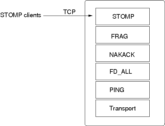
The STOMP protocol should be near the top of the stack.
A STOMP instance listens on a TCP socket for client connections. The port and bind address of the server socket can be defined via properties.
A client can send SUBSCRIBE commands for various destinations. When a SEND for a given destination is received, STOMP adds a header to the message and broadcasts it to all cluster nodes. Every node then in turn forwards the message to all of its connected clients which have subscribed to the same destination. When a destination is not given, STOMP simply forwards the message to all connected clients.
Traffic can be generated by clients and by servers. In the latter case, we could for example have code executing in the address space of a JGroups (server) node. In the former case, clients use the SEND command to send messages to a JGroups server and receive messages via the MESSAGE command. If there is code on the server which generates messages, it is important that both client and server code agree on a marshalling format, e.g. JSON, so that they understand each other's messages.
Clients can be written in any language, as long as they understand the STOMP protocol. Note that the JGroups STOMP protocol implementation sends additional information (e.g. INFO) to clients; non-JGroups STOMP clients should simply ignore them.
JGroups comes with a STOMP client (org.jgroups.client.StompConnection) and a demo (StompDraw). Both need to be started with the address and port of a JGroups cluster node. Once they have been started, the JGroups STOMP protocol will notify clients of cluster changes, which is needed so client can failover to another JGroups server node when a node is shut down. E.g. when a client connects to C, after connection, it'll get a list of endpoints (e.g. A,B,C,D). When C is terminated, or crashes, the client automatically reconnects to any of the remaining nodes, e.g. A, B, or D. When this happens, a client is also re-subscribed to the destinations it registered for.
The JGroups STOMP protocol can be used when we have clients, which are either not in the same network segment as the JGroups server nodes, or which don't want to become full-blown JGroups server nodes. Figure 5.5, “STOMP architecture” shows a typical setup.
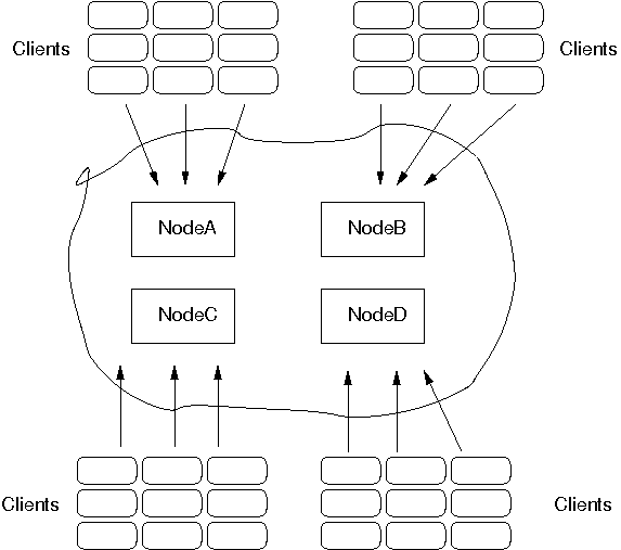
There are 4 nodes in a cluster. Say the cluster is in a LAN, and communication is via IP multicasting (UDP as transport). We now have clients which do not want to be part of the cluster themselves, e.g. because they're in a different geographic location (and we don't want to switch the main cluster to TCP), or because clients are frequently started and stopped, and therefore the cost of startup and joining wouldn't be amortized over the lifetime of a client. Another reason could be that clients are written in a different language, or perhaps, we don't want a large cluster, which could be the case if we for example have 10 JGroups server nodes and 1000 clients connected to them.
In the example, we see 9 clients connected to every JGroups cluster node. If a client connected to node A sends a message to destination /topics/chat, then the message is multicast from node A to all other nodes (B, C and D). Every node then forwards the message to those clients which have previously subscribed to /topics/chat.
When node A crashes (or leaves) the JGroups STOMP clients (org.jgroups.client.StompConnection) simply pick another server node and connect to it.
For more information about STOMP see the blog entry at http://belaban.blogspot.com/2010/10/stomp-for-jgroups.html.
In 2.12, the RELAY protocol was added to JGroups (for the properties see Section 7.14.5, “RELAY”). It allows for bridging of remote clusters. For example, if we have a cluster in New York (NYC) and another one in San Francisco (SFO), then RELAY allows us to bridge NYC and SFO, so that multicast messages sent in NYC will be forwarded to SFO and vice versa.
The NYC and SFO clusters could for example use IP multicasting (UDP as transport), and the bridge could use TCP as transport. The SFO and NYC clusters don't even need to use the same cluster name.
Figure 5.6, “Relaying between different clusters” shows how the two clusters are bridged.
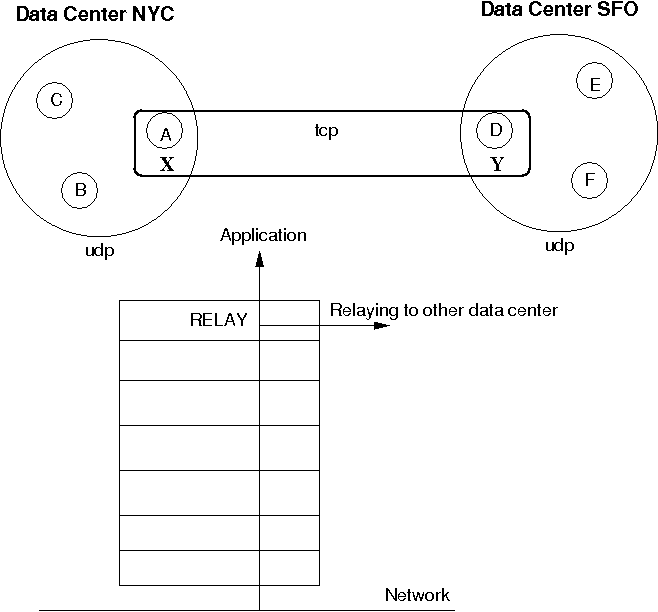
The cluster on the left side with nodes A (the coordinator), B and C is called "NYC" and use IP multicasting (UDP as transport). The cluster on the right side ("SFO") has nodes D (coordinator), E and F.
The bridge between the local clusters NYC and SFO is essentially another cluster with the coordinators (A and D) of the local clusters as members. The bridge typically uses TCP as transport, but any of the supported JGroups transports could be used (including UDP, if supported across a WAN, for instance).
Only a coordinator relays traffic between the local and remote cluster. When A crashes or leaves, then the next-in-line (B) takes over and starts relaying.
Relaying is done via the RELAY protocol added to the top of the stack. The bridge is configured with the bridge_props property, e.g. bridge_props="/home/bela/tcp.xml". This creates a JChannel inside RELAY.
Note that property "site" must be set in both subclusters. In the example above, we could set site="nyc" for the NYC subcluster and site="sfo" for the SFO ubcluster.
The design is described in detail in JGroups/doc/design/RELAY.txt (part of the source distribution). In a nutshell, multicast messages received in a local cluster are wrapped and forwarded to the remote cluster by a relay (= the coordinator of a local cluster). When a remote cluster receives such a message, it is unwrapped and put onto the local cluster.
JGroups uses subclasses of UUID (PayloadUUID) to ship the site name with an address. When we see an address with site="nyc" on the SFO side, then RELAY will forward the message to the SFO subcluster, and vice versa. When C multicasts a message in the NYC cluster, A will forward it to D, which will re-broadcast the message on its local cluster, with the sender being D. This means that the sender of the local broadcast will appear as D (so all retransmit requests got to D), but the original sender C is preserved in the header. At the RELAY protocol, the sender will be replaced with the original sender (C) having site="nyc". When node F wants to reply to the sender of the multicast, the destination of the message will be C, which is intercepted by the RELAY protocol and forwarded to the current relay (D). D then picks the correct destination (C) and sends the message to the remote cluster, where A makes sure C (the original sender) receives it.
An important design goal of RELAY is to be able to have completely autonomous clusters, so NYC doesn't for example have to block waiting for credits from SFO, or a node in the SFO cluster doesn't have to ask a node in NYC for retransmission of a missing message.
RELAY presents a global view to the application, e.g. a view received by nodes could be {D,E,F,A,B,C}. This view is the same on all nodes, and a global view is generated by taking the two local views, e.g. A|5 {A,B,C} and D|2 {D,E,F}, comparing the coordinators' addresses (the UUIDs for A and D) and concatenating the views into a list. So if D's UUID is greater than A's UUID, we first add D's members into the global view ({D,E,F}), and then A's members.
Therefore, we'll always see all of A's members, followed by all of D's members, or the other way round.
To see which nodes are local and which ones remote, we can iterate through the addresses (PayloadUUID) and use the site (PayloadUUID.getPayload()) name to for example differentiate between "nyc" and "sfo".
To setup a relay, we need essentially 3 XML configuration files: 2 to configure the local clusters and 1 for the bridge.
To configure the first local cluster, we can copy udp.xml from the JGroups distribution and add RELAY on top of it: <RELAY bridge_props="/home/bela/tcp.xml" />. Let's say we call this config relay.xml.
The second local cluster can be configured by copying relay.xml to relay2.xml. Then change the mcast_addr and/or mcast_port, so we actually have 2 different cluster in case we run instances of both clusters in the same network. Of course, if the nodes of one cluster are run in a different network from the nodes of the other cluster, and they cannot talk to each other, then we can simply use the same configuration.
The 'site' property needs to be configured in relay.xml and relay2.xml, and it has to be different. For example, relay.xml could use site="nyc" and relay2.xml could use site="sfo".
The bridge is configured by taking the stock tcp.xml and making sure both local clusters can see each other through TCP.
Note
RELAY2 was added to JGroups in the 3.2 release.
Similar to Section 5.10, “Bridging between remote clusters”, RELAY2 provides clustering between sites. However, the differences to RELAY are:
- Clustering can be done between multiple sites. Currently (3.2), sites have to be directly reachable. In 3.3, hierarchical setups of sites will be implemented.
- Virtual (global) views are not provided anymore. If we have clusters SFO={A,B,C} and LON={X,Y,Z}, then both clusters are completed autonomous and don't know about each other's existence.
- Not only unicasts, but also multicasts can be routed between sites (configurable).
To use RELAY2, it has to be placed at the top of the configuration, e.g.:
<relay.RELAY2 site="LON" config="/home/bela/relay2.xml"

              relay_multicasts="true" />

<FORWARD_TO_COORD />
The above configuration has a site name which will be used to route messages between sites. To do that, addresses contain the site-ID, so we always know which site the address is from. E.g. an address A1:LON in the SFO site is not local, but will be routed to the remote site SFO.
The FORWARD_TO_COORD protocol is optional, but since it guarantees reliable message forwarding to the local site master, it is recommended. It makes sure that - if a local coordinator (site master) crashes or leaves while a message is being forwarded to it - the message will be forwarded to the next coordinator once elected.
The relay_multicasts property determines whether or not multicast messages (with dest = null) are relayed to the other sites, or not. When we have a site LON, connected to sites SFO and NYC, if a multicast message is sent in site LON, and relay_multicasts is true, then all members of sites SFO and NYC will receive the message.
The config property points to an XML file which defines the setup of the sites, e.g.:
<RelayConfiguration xmlns="urn:jgroups:relay:1.0">


    <sites>

        <site name="lon" id="0">

            <bridges>

                <bridge config="/home/bela/global.xml" name="global"/>

            </bridges>

        </site>


        <site name="nyc" id="1">

            <bridges>

                <bridge config="/home/bela/global.xml" name="global"/>

            </bridges>

        </site>


        <site name="sfo" id="2">

            <bridges>

                <bridge name="global" config="/home/bela/global.xml"/>

            </bridges>

        </site>

    </sites>

</RelayConfiguration>
Note
The configuration as shown above might change in 3.3, when hierarchical routing will be added.
This defines 3 sites LON, SFO and NYC. All the sites are connected to a global cluster (bus) "global" (defined by /home/bela/global.xml). All inter-site traffic will be sent via this global cluster (which has to be accessible by all of the sites). Intra-site traffic is sent via the cluster that's defined by the configuration of which RELAY2 is the top protocol.
The above configuration is not mandatory, ie. instead of a global cluster, we could define separate clusters between LON and SFO and LON and NYC. However, in such a setup, due to lack of hierarchical routing, NYC and SFO wouldn't be able to send each other messages; only LON would be able to send message to SFO and NYC.
If relay_multicasts is true then any multicast received by the site master of a site (ie. the coordinator of the local cluster, responsible for relaying of unicasts and multicasts) will relay the multicast to all connected sites. This means that - beyond setting relay_multicasts - nothing has to be done in order to relay multicasts across all sites.
A recipient of a multicast message which originated from a different site will see that the sender's address is not a UUID, but a subclass (SiteUUID) which is the UUID plus the site suffix, e.g. A1:SFO. Since a SiteUUID is a subclass of a UUID, both types can be mixed and matched, placed into hashmaps or lists, and they implement compareTo() and equals() correctly.
When a reply is to be sent to the originator of the multicast message, Message.getSrc() provides the target address for the unicast response message. This is also a SiteUUID, but the sender of the response neither has to know nor take any special action to send the response, as JGroups takes care of routing the response back to the original sender.
As discussed above, relaying of unicasts is done transparently. However, if we don't have a target address (e.g. as a result of reception of a multicast), there is a special address SiteMaster which identifies the site master; the coordinator of a local cluster responsible for relaying of messages.
Class SiteMaster is created with the name of a site, e.g. new SiteMaster("LON"). When a unicast with destination SiteMaster("LON") is sent, then we relay the message to the current site master of LON. If the site master changes, messages will get relayed to a different node, which took over the role of the site master from the old (perhaps crashed) site master.
Sometimes only certain members of a site should become site masters; e.g. the more powerful boxes (as routing needs some additional CPU power), or multi-homed hosts which are connected to the external network (over which the sites are connected with each other).
To do this, RELAY2 can generate special addresses which contain the knowledge about whether a member should be skipped when selecting a site master from a view, or not. If can_become_site_master is set to false in RELAY2, then the selection process will skip that member. However, if all members in a given view are marked with can_become_site_master=false, then the first member of the view will get picked.
When we have all members in a view marked with can_become_site_master=false, e.g. {B,C,D}, then B is the site master. If we now start a member A with can_become_site_master=true, then B will stop being the site master and A will become the new site master.
Invoking RPCs across sites is more or less transparent, except for the case when we cannot reach a member of a remote site. If we want to invoke method foo() in A1, A2 (local) and SiteMaster("SFO"), we could write the following code:
List<Address> dests=new ArrayList<Address>(view.getMembers());

dests.add(new SiteMaster("SFO"));

RspList<Object> rsps;

rsps=disp.callRemoteMethods(dests, call,

              new RequestOptions(ResponseMode.GET_ALL, 5000).setAnycasting(true));

for(Rsp rsp: rsps.values()) {

    if(rsp.wasUnreachable())

        System.out.println("<< unreachable: " + rsp.getSender());

    else

        System.out.println("<< " + rsp.getValue() + " from " + rsp.getSender());

}
First, we add the members (A1 and A2) of the current (local) view to the destination set. Then we add the special address SiteMaster("SFO") which acts as a placeholder for the current coordinator of the SFO site.
Next, we invoke the call with dests as target set and block until responses from all A1, A2 and SiteMaster("SFO") have been received, or until 5 seconds have elapsed.
Next, we check the response list. And here comes the bit that's new in 3.2: if a site is unreachable, a Rsp has an additional field "unreachable", which means that we could not reach the site master of SFO for example. Note that this is not necessarily an error, as a site maybe currently down, but the caller now has the option of checking on this new status field.
Let's configure an example which consists of 3 sites SFO, LON and NYC and 2 members in each site. First we define the configuration for the local cluster (site) SFO. To do this, we could for example copy udp.xml from the JGroups distro (and name it sfo.xml) and add RELAY2 to the top (as shown above). RELAY2's config property points to relay2.xml as shown above as well. The relay2.xml file defines a global cluster with global.xml, which uses TCP and MPING for the global cluster (copy for example tcp.xml to create global.xml)
Now copy sfo.xml to lon.xml and nyc.xml. The RELAY2 configuration stays the same for lon.xml and nyc.xml, but the multicast address and/or multicast port has to be changed in order to create 3 separate local clusters. Therefore, modify both lon.xml and nyc.xml and change mcast_port and / or mcast_addr in UDP to use separate values, so the clusters don't interfere with each other.
To test whether we have 3 different clusters, start the Draw application (shipped with JGroups):
java -Djava.net.preferIPv4Stack=true org.jgroups.demos.Draw -props ./sfo.xml -name sfo1
java -Djava.net.preferIPv4Stack=true org.jgroups.demos.Draw -props ./sfo.xml -name sfo2
java -Djava.net.preferIPv4Stack=true org.jgroups.demos.Draw -props ./lon.xml -name lon1
java -Djava.net.preferIPv4Stack=true org.jgroups.demos.Draw -props ./lon.xml -name lon2
java -Djava.net.preferIPv4Stack=true org.jgroups.demos.Draw -props ./nyc.xml -name nyc1
java -Djava.net.preferIPv4Stack=true org.jgroups.demos.Draw -props ./nyc.xml -name nyc2
We should now have 3 local clusters (= sites) of 2 instances each. When RELAY2.relay_multicasts is true, if you draw in one instance, we should see the drawing in all 6 instances. This means that relaying of multicasting between sites works. If this doesn't work, run a few Draw instances on global.xml, to see if they find each other.
Note that the first member of each cluster always joins the global cluster (defined by global.xml) too. This is necessary to relay messages between sites.
To test unicasts between sites, you can use the org.jgroups.demos.RelayDemoRpc program: start it as follows:
java -Djava.net.preferIPv4Stack=true org.jgroups.demos.RelayDemoRpc -props ./sfo.xml -name sfo1
Start 2 instances in 3 sites and then use
mcast lon sfo nyc
to invoke RPCs on all local members and site masters SFO, NYC and LON. If one of the sites is down, you'll get a message stating the site is unreachable.
Daisychaining refers to a way of disseminating messages sent to the entire cluster.
The idea behind it is that it is inefficient to broadcast a message in clusters where IP multicasting is not available. For example, if we only have TCP available (as is the case in most clouds today), then we have to send a broadcast (or group) message N-1 times. If we want to broadcast M to a cluster of 10, we send the same message 9 times.
Example: if we have {A,B,C,D,E,F}, and A broadcasts M, then it sends it to B, then to C, then to D etc. If we have a 1 GB switch, and M is 1GB, then sending a broadcast to 9 members takes 9 seconds, even if we parallelize the sending of M. This is due to the fact that the link to the switch only sustains 1GB / sec. (Note that I'm conveniently ignoring the fact that the switch will start dropping packets if it is overloaded, causing TCP to retransmit, slowing things down)...
Let's introduce the concept of a round. A round is the time it takes to send or receive a message. In the above example, a round takes 1 second if we send 1 GB messages. In the existing N-1 approach, it takes X * (N-1) rounds to send X messages to a cluster of N nodes. So to broadcast 10 messages a the cluster of 10, it takes 90 rounds.
Enter DAISYCHAIN.
The idea is that, instead of sending a message to N-1 members, we only send it to our neighbor, which forwards it to its neighbor, and so on. For example, in {A,B,C,D,E}, D would broadcast a message by forwarding it to E, E forwards it to A, A to B, B to C and C to D. We use a time-to-live field, which gets decremented on every forward, and a message gets discarded when the time-to-live is 0.
The advantage is that, instead of taxing the link between a member and the switch to send N-1 messages, we distribute the traffic more evenly across the links between the nodes and the switch. Let's take a look at an example, where A broadcasts messages m1 and m2 in cluster {A,B,C,D}, '-->' means sending:
- Round 1: A(m1) --> B
- Round 2: A(m1) --> C
- Round 3: A(m1) --> D
- Round 4: A(m2) --> B
- Round 5: A(m2) --> C
- Round 6: A(m2) --> D
It takes 6 rounds to broadcast m1 and m2 to the cluster.
- Round 1: A(m1) --> B
- Round 2: A(m2) --> B || B(m1) --> C
- Round 3: B(m2) --> C || C(m1) --> D
- Round 4: C(m2) --> D
In round 1, A send m1 to B.
In round 2, A sends m2 to B, but B also forwards m1 (received in round 1) to C.
In round 3, A is done. B forwards m2 to C and C forwards m1 to D (in parallel, denoted by '||').
In round 4, C forwards m2 to D.
Let's take a look at this in terms of switch usage: in the N-1 approach, A can only send 125MB/sec, no matter how many members there are in the cluster, so it is constrained by the link capacity to the switch. (Note that A can also receive 125MB/sec in parallel with today's full duplex links).
So the link between A and the switch gets hot.
In the daisychaining approach, link usage is more even: if we look for example at round 2, A sending to B and B sending to C uses 2 different links, so there are no constraints regarding capacity of a link. The same goes for B sending to C and C sending to D.
In terms of rounds, the daisy chaining approach uses X + (N-2) rounds, so for a cluster size of 10 and broadcasting 10 messages, it requires only 18 rounds, compared to 90 for the N-1 approach !
To measure performance of DAISYCHAIN, a performance test (test.Perf) was run, with 4 nodes connected to a 1 GB switch; and every node sending 1 million 8K messages, for a total of 32GB received by every node. The config used was tcp.xml.
The N-1 approach yielded a throughput of 73 MB/node/sec, and the daisy chaining approach 107MB/node/sec !
A message can be tagged with a selection of flags, which alter the way certain protocols treat the message. This is done as follows:
Message msg=new Message();

msg.setFlag(Message.OOB);

msg.setFlag(Message.NO_FC);
Here we tag the message to be OOB (out of band) and to bypass flow control.
The advantage of tagging messages is that we don't need to change the configuration, but instead can override it on a per-message basis.
The available flags are:
- Message.OOB
This tags a message as out-of-band, which will get it processed by the out-of-band thread pool at the receiver's side. Note that an OOB message does not provide any ordering guarantees, although OOB messages are reliable (no loss) and are delivered only once. See Section 5.4.5, “Out-of-band messages” for details.
- Message.DONT_BUNDLE
This flag causes the transport not to bundle the message, but to send it immediately.
See Section 5.3.1.1, “Message bundling and performance” for a discussion of the DONT_BUNDLE flag with respect to performance of blocking RPCs.
- Message.NO_FC
This flag bypasses any flow control protocol (see Section 7.9, “Flow control”) for a discussion of flow control protocols.
- Message.SCOPED
This flag is set automatically when
Message.setScope()is called. See Section 5.4.4, “Scopes: concurrent message delivery for messages from the same sender” for a discussion on scopes.- Message.NO_RELIABILITY
When sending unicast or multicast messages, some protocols (UNICAST, NAKACK) add sequence numbers to the messages in order to (1) deliver them reliably and (2) in order.
If we don't want reliability, we can tag the message with flag NO_RELIABILITY. This means that a message tagged with this flag may not be received, may be received more than once, or may be received out of order.
A message tagged with NO_RELIABILITY will simply bypass reliable protocols such as UNICAST and NAKACK.
For example, if we send multicast message M1, M2 (NO_RELIABILITY), M3 and M4, and the starting sequence number is #25, then M1 will have seqno #25, M3 will have #26 and M4 will have #27. We can see that we don't allocate a seqno for M2 here.
- Message.NO_TOTAL_ORDER
If we use a total order configuration with SEQUENCER (Section 7.11.1, “SEQUENCER”), then we can bypass SEQUENCER (if we don't need total order for a given message) by tagging the message with
NO_TOTAL_ORDER.- Message.NO_RELAY
If we use RELAY (see Section 5.10, “Bridging between remote clusters”) and don't want a message to be relayed to the other site(s), then we can tag the message with NO_RELAY.
- Message.RSVP
When this flag is set, a message send will block until the receiver (unicast) or receivers (multicast) have acked reception of the message, or until a timeout occurs. See Section 3.8.8.2, “Synchronous messages” for details.
There are a number of performance tests shipped with JGroups. The section below discusses MPerf, which is a replacement for (static) perf.Test. This change was done in 3.1.
MPerf is a test which measures multicast performance. This doesn't mean IP multicast performance, but point-to-multipoint performance. Point-to-multipoint means that we measure performance of one-to-many messages; in other words, messages sent to all cluster members.
Compared to the old perf.Test, MPerf is dynamic; it doesn't need a setup file to define the number of senders, number of messages to be sent and message size. Instead, all the configuration needed by an instance of MPerf is an XML stack configuration, and configuration changes done in one member are automatically broadcast to all other members.
MPerf can be started as follows:
java -cp $CLASSPATH -Djava.net.preferIPv4Stack=true org.jgroups.tests.perf.MPerf -props ./fast.xml
This assumes that we're using IPv4 addresses (otherwise IPv6 addresses are used) and the JGroups JAR on CLASSPATH.
A screen shot of MPerf looks like this (could be different, depending on the JGroups version):
[linux]/home/bela$ mperf.sh -props ./fast.xml -name B

----------------------- MPerf -----------------------
Date: Mon Dec 12 15:33:21 CET 2011
Run by: bela
JGroups version: 3.1.0.Alpha1

-------------------------------------------------------------------
GMS: address=B, cluster=mperf, physical address=192.168.1.5:46614
-------------------------------------------------------------------
** [A|9] [A, B]
num_msgs=1000000
msg_size=1000
num_threads=1
[1] Send [2] View
[3] Set num msgs (1000000) [4] Set msg size (1KB) [5] Set threads (1)
[6] New config (./fast.xml)
[x] Exit this [X] Exit all
We're starting MPerf with -props ./fast.xml and -name B. The -props option
points to a JGroups configuration file, and -name gives the member the name "B".
MPerf can then be run by pressing [1]. In this case, every member in the cluster (in the example, we have members A and B) will send 1 million 1K messages. Once all messages have been received, MPerf will write a summary of the performance results to stdout:
[1] Send [2] View
[3] Set num msgs (1000000) [4] Set msg size (1KB) [5] Set threads (1)
[6] New config (./fast.xml)
[x] Exit this [X] Exit all
1
-- sending 1000000 msgs
++ sent 100000
-- received 200000 msgs (1410 ms, 141843.97 msgs/sec, 141.84MB/sec)
++ sent 200000
-- received 400000 msgs (1326 ms, 150829.56 msgs/sec, 150.83MB/sec)
++ sent 300000
-- received 600000 msgs (1383 ms, 144613.16 msgs/sec, 144.61MB/sec)
++ sent 400000
-- received 800000 msgs (1405 ms, 142348.75 msgs/sec, 142.35MB/sec)
++ sent 500000
-- received 1000000 msgs (1343 ms, 148920.33 msgs/sec, 148.92MB/sec)
++ sent 600000
-- received 1200000 msgs (1700 ms, 117647.06 msgs/sec, 117.65MB/sec)
++ sent 700000
-- received 1400000 msgs (1399 ms, 142959.26 msgs/sec, 142.96MB/sec)
++ sent 800000
-- received 1600000 msgs (1359 ms, 147167.03 msgs/sec, 147.17MB/sec)
++ sent 900000
-- received 1800000 msgs (1689 ms, 118413.26 msgs/sec, 118.41MB/sec)
++ sent 1000000
-- received 2000000 msgs (1519 ms, 131665.57 msgs/sec, 131.67MB/sec)

Results:

B: 2000000 msgs, 2GB received, msgs/sec=137608.37, throughput=137.61MB
A: 2000000 msgs, 2GB received, msgs/sec=137959.58, throughput=137.96MB

===============================================================================
 Avg/node:    2000000 msgs, 2GB received, msgs/sec=137788.49, throughput=137.79MB
 Avg/cluster: 4000000 msgs, 4GB received, msgs/sec=275576.99, throughput=275.58MB
================================================================================


[1] Send [2] View
[3] Set num msgs (1000000) [4] Set msg size (1KB) [5] Set threads (1) [6] New config (./fast.xml)
[x] Exit this [X] Exit all
In the sample run above, we see member B's screen. B sends 1 million messages and waits for its 1 million and the 1 million messages from B to be received before it dumps some stats to stdout. The stats include the number of messages and bytes received, the time, the message rate and throughput averaged over the 2 members. It also shows the aggregated performance over the entire cluster.
In the sample run above, we got an average 137MB of data per member per second, and an aggregated 275MB per second for the entire cluster (A and B in this case).
Parameters such as the number of messages to be sent, the message size and the number of threads to be used to send the messages can be configured by pressing the corresponding numbers. After pressing return, the change will be broadcast to all cluster members, so that we don't have to go to each member and apply the same change. Also, new members started, will fetch the current configuration and apply it.
For example, if we set the message size in A to 2000 bytes, then the change would be sent to B, which would apply it as well. If we started a third member C, it would also have a configuration with a message size of 2000.
Another feature is the ability to restart all cluster members with a new configuration. For example, if
we modified ./fast.xml, we could select [6] to make all cluster members disconnect and
close their existing channels and start a new channel based on the modified fast.xml configuration.
The new configuration file doesn't even have to be accessible on all cluster members; only on the member which makes the change. The file contents will be read by that member, converted into a byte buffer and shipped to all cluster members, where the new channel will then be created with the byte buffer (converted into an input stream) as config.
Being able to dynamically change the test parameters and the JGroups configuration makes MPerf suited to be run in larger clusters; unless a new JGroups version is installed, MPerf will never have to be restarted manually.
Ergonomics is similar to the dynamic setting of optimal values for the JVM, e.g. garbage collection, memory sizes etc. In JGroups, ergonomics means that we try to dynamically determine and set optimal values for protocol properties. Examples are thread pool size, flow control credits, heartbeat frequency and so on.
There is an ergonomics property which can be enabled or disabled for every protocol.
The default is true. To disable it, set it to false, e.g.:
<UDP... />

<PING ergonomics="false"/>
Here we leave ergonomics enabled for UDP (the default is true), but disable it for PING.
Ergonomics is work-in-progress, and will be implemented over multiple releases.
SUPERVISOR (Section 7.14.13, “SUPERVISOR”) provides a rule based fault detection and correction protocol. It allows for rules to be installed, which are periodically invoked. When invoked, a condition can be checked and corrective action can be taken to fix the problem. Essentially, SUPERVISOR acts like a human administrator, except that condition checking and action triggering is done automatically.
An example of a rule is org.jgroups.protocols.rules.CheckFDMonitor: invoked periodically, it checks if the monitor task in FD is running when the membership is 2 or more and - if not - restarts it. The sections below show how to write the rule and how to invoke it.
All rules to be installed in SUPERVISOR are listed in an XML file, e.g. rules.xml:
<rules xmlns="urn:jgroups:rules:1.0">

     <rule name="rule1" class="org.jgroups.protocols.rules.CheckFDMonitorRule"

           interval="1000"/>

</rules>
There is only one rule "rule1" present, which is run every second. The name of the class implementing the rule is "org.jgroups.protocols.rules.CheckFDMonitorRule", and its implementation is:
public class CheckFDMonitor extends Rule {

    protected FD fd;


    public String name() {return "sample";}


    public String description() {

        return "Starts FD.Monitor if membership > 1 and monitor isn't running";

    }


    public void init() {

        super.init();

        fd=(FD)sv.getProtocolStack().findProtocol(FD.class);

        if(fd == null) {

            log.info("FD was not found, uninstalling myself (sample)");

            sv.uninstallRule("sample");

        }

    }


    public boolean eval() {

        return sv.getView() != null && sv.getView().size() > 1

            && !fd.isMonitorRunning();

    }


    public String condition() {

        View view=sv.getView();

        return "Membership is " + (view != null? view.size() : "n/a") +

            ", FD.Monitor running=" + fd.isMonitorRunning();

    }


    public void trigger() throws Throwable {

        System.out.println(sv.getLocalAddress() + ": starting failure detection");

        fd.startFailureDetection();

    }

}
CheckFDMonitor extends abstract class Rule which sets a reference to SUPERVISOR and the log when the rule has been installed.
Method name() needs to return a unique name by which the rule can be uninstalled later if necessary.
Description() should provide a meaningful description (used by JMX).
In init(), a reference to FD is set by getting the protocol stack from the SUPERVISOR (sv). If not found, e.g. because there is no FD protocol present in a given stack, the rule uninstalls itself.
Method eval() is called every second. It checks that the monitor task in FD is running (when the membership is 2 or more) and, if not, returns true. In that case, method trigger() will get called by the code in the Rule superclass and it simply restarts the stopped monitor task.
Note that rules can be installed and uninstalled dynamically at runtime, e.g. via probe.sh:
probe.sh op=SUPERVISOR.installRule["myrule", 1000,"org.jgroups.protocols.rules.CheckFDMonitor"]
installs rule CheckFDMonitor as "myrule" into the running system, and this rule will be run every 1000 ms.
probe.sh op=SUPERVISOR.uninstallRule["myrule"]
uninstalls "myrule" again.
probe.sh op=SUPERVISOR.dumpRules
dumps a list of currently installed rules to stdout.
Probe is the Swiss Army Knife for JGroups; it allows to fetch information about the members running in a cluster, get and set properties of the various protocols, and invoke methods in all cluster members.
Probe can even insert protocols into running cluster members, or remove/replace existing protocols. Note that this doesn't make sense though with stateful protocols such as NAKACK. But this feature is helpful, it could be used for example to insert a diagnostics or stats protocol into a running system. When done, the protocol can be removed again.
Probe is a script (probe.sh in the bin directory of the source
distribution) that can be invoked on any of the hosts in same network in which a cluster is running.
Note
Probe currently requires IP multicasting to be enabled in a network, in order to discover the cluster members in a network. It can be used with TCP as transport, but still requires multicasting.
The probe.sh script essentially calls org.jgroups.tests.Probe which is part of
the JGroups JAR.
The way probe works is that every stack has an additional multicast socket that by default listens on 224.0.75.75:7500 for diagnostics requests from probe. The configuration is located in the transport protocol (e.g. UDP), and consists of the following properties:
Table 5.3. Properties for diagnostics / probe
| Name | Description |
|---|---|
| enable_diagnostics | Whether or not to enable diagnostics (default: true). When enabled, this will create a MulticastSocket and we have one additional thread listening for probe requests. When disabled, we'll have neither the thread nor the socket created. |
| diagnostics_addr |
The multicast address which the MulticastSocket should join. The default is
"224.0.75.75" for IPv4 and "ff0e::0:75:75" for IPv6.
|
| diagnostics_port | The port on which the MulticastSocket should listen. The default is 7500. |
Probe is extensible; by implementing a ProbeHandler and registering it with the
transport (TP.registerProbeHandler()), any protocol, or even
applications can register functionality to be invoked via probe. Refer to the
javadoc for details.
To get information about the cluster members running in the local network, we can use the following
probe command (note that probe could also be invoked as
java -classpath $CP org.jgroups.tests.Probe $*):
[linux]/home/bela/JGroups$ probe.sh

-- send probe on /224.0.75.75:7500


#1 (149 bytes):
local_addr=A [1a1f543c-2332-843b-b523-8d7653874de7]
cluster=DrawGroupDemo
view=[A|1] [A, B]
physical_addr=192.168.1.5:43283
version=3.0.0.Beta1


#2 (149 bytes):
local_addr=B [88588976-5416-b054-ede9-0bf8d4b56c02]
cluster=DrawGroupDemo
view=[A|1] [A, B]
physical_addr=192.168.1.5:35841
version=3.0.0.Beta1


2 responses (2 matches, 0 non matches)
[linux]/home/bela/JGroups$
This gets us 2 responses, from A and B. "A" and "B" are the logical names, but we also see the UUIDs.
They're both in the same cluster ("DrawGroupDemo") and both have the same view
([A|1] [A, B]). The physical address and the version of both members is also shown.
Note that probe.sh -help lists the command line options.
To fetch all of the JMX information from all protocols, we can invoke
probe jmx
However, this dumps all of the JMX attributes from all protocols of all cluster members, so make sure to pipe the output into a file and awk and sed it for legibility !
However, we can also JMX information from a specific protocol, e.g. FRAG2 (slightly edited>:
[linux]/home/bela$ probe.sh  jmx=FRAG2

-- send probe on /224.0.75.75:7500


#1 (318 bytes):
local_addr=B [88588976-5416-b054-ede9-0bf8d4b56c02]
cluster=DrawGroupDemo
physical_addr=192.168.1.5:35841
jmx=FRAG2={id=5, level=off, num_received_msgs=131, frag_size=60000,
           num_sent_msgs=54, stats=true, num_sent_frags=0,
           name=FRAG2, ergonomics=true, num_received_frags=0}

view=[A|1] [A, B]
version=3.0.0.Beta1


#2 (318 bytes):
local_addr=A [1a1f543c-2332-843b-b523-8d7653874de7]
cluster=DrawGroupDemo
physical_addr=192.168.1.5:43283
jmx=FRAG2={id=5, level=off, num_received_msgs=131, frag_size=60000,
           num_sent_msgs=77, stats=true, num_sent_frags=0,
           name=FRAG2, ergonomics=true, num_received_frags=0}

view=[A|1] [A, B]
version=3.0.0.Beta1


2 responses (2 matches, 0 non matches)
[linux]/home/bela$
We can also get information about specific properties in a given protocol:
[linux]/home/bela$ probe.sh  jmx=NAKACK.xmit

-- send probe on /224.0.75.75:7500


#1 (443 bytes):
local_addr=A [1a1f543c-2332-843b-b523-8d7653874de7]
cluster=DrawGroupDemo
physical_addr=192.168.1.5:43283
jmx=NAKACK={xmit_table_max_compaction_time=600000, xmit_history_max_size=50,
            xmit_rsps_sent=0, xmit_reqs_received=0, xmit_table_num_rows=5,
            xmit_reqs_sent=0, xmit_table_resize_factor=1.2,
            xmit_from_random_member=false, xmit_table_size=78,
            xmit_table_msgs_per_row=10000, xmit_rsps_received=0}

view=[A|1] [A, B]
version=3.0.0.Beta1


#2 (443 bytes):
local_addr=B [88588976-5416-b054-ede9-0bf8d4b56c02]
cluster=DrawGroupDemo
physical_addr=192.168.1.5:35841
jmx=NAKACK={xmit_table_max_compaction_time=600000, xmit_history_max_size=50,
            xmit_rsps_sent=0, xmit_reqs_received=0, xmit_table_num_rows=5,
            xmit_reqs_sent=0, xmit_table_resize_factor=1.2,
            xmit_from_random_member=false, xmit_table_size=54,
            xmit_table_msgs_per_row=10000, xmit_rsps_received=0}

view=[A|1] [A, B]
version=3.0.0.Beta1


2 responses (2 matches, 0 non matches)
[linux]/home/bela$
This returns all JMX attributes that start with "xmit" in all NAKACK protocols of
all cluster members. We can also pass a list of attributes:
[linux]/home/bela$ probe.sh  jmx=NAKACK.missing,xmit

-- send probe on /224.0.75.75:7500


#1 (468 bytes):
local_addr=A [1a1f543c-2332-843b-b523-8d7653874de7]
cluster=DrawGroupDemo
physical_addr=192.168.1.5:43283
jmx=NAKACK={xmit_table_max_compaction_time=600000, xmit_history_max_size=50,
            xmit_rsps_sent=0, xmit_reqs_received=0, xmit_table_num_rows=5,
            xmit_reqs_sent=0, xmit_table_resize_factor=1.2,
            xmit_from_random_member=false, xmit_table_size=78,
            missing_msgs_received=0, xmit_table_msgs_per_row=10000,
            xmit_rsps_received=0}

view=[A|1] [A, B]
version=3.0.0.Beta1


#2 (468 bytes):
local_addr=B [88588976-5416-b054-ede9-0bf8d4b56c02]
cluster=DrawGroupDemo
physical_addr=192.168.1.5:35841
jmx=NAKACK={xmit_table_max_compaction_time=600000, xmit_history_max_size=50,
            xmit_rsps_sent=0, xmit_reqs_received=0, xmit_table_num_rows=5,
            xmit_reqs_sent=0, xmit_table_resize_factor=1.2,
            xmit_from_random_member=false, xmit_table_size=54,
            missing_msgs_received=0, xmit_table_msgs_per_row=10000,
            xmit_rsps_received=0}

view=[A|1] [A, B]
version=3.0.0.Beta1


2 responses (2 matches, 0 non matches)
[linux]/home/bela$
This returns all attributes of NAKACK that start with "xmit" or "missing".
To invoke an operation, e.g. to set the logging level in all UDP protocols from "warn" to "trace", we
can use probe.sh op=UPD.setLevel["trace"]. This raises the logging level in all
UDP protocols of all cluster members, which is useful to diagnose a running system.
Operation invocation uses reflection, so any method defined in any protocol can be invoked. This is a powerful tool to get diagnostics information from a running cluster.
For further information, refer to the command line options of probe
(probe.sh -h).
[5] Although not as efficient (and using more bandwidth), it is sometimes the only possibility to reach group members.
[6] To do so, GossipRouter maintains a mapping between cluster names and member addresses, and TCP connections.
[7] Currently, SocketFactory does not support creation of NIO sockets / channels.
[8] Note that block() will be called in a Receiver when the flush is about to start and unblock() will be called when it ends