Copyright Red Hat 1998 - 2035
This document is licensed under the "Creative Commons Attribution-ShareAlike (CC-BY-SA) 3.0" license.
This is the JGroups manual. It provides information about:
-
Installation and configuration
-
Using JGroups (the API)
-
Configuration of the JGroups protocols
The focus is on how to use JGroups, not on how JGroups is implemented.
Here are a couple of points I want to abide by throughout this book:
-
I like brevity. I will strive to describe concepts as clearly as possible (for a non-native English speaker) and will refrain from saying more than I have to to make a point.
-
I like simplicity. Keep It Simple and Stupid. This is one of the biggest goals I have both in writing this manual and in writing JGroups. It is easy to explain simple concepts in complex terms, but it is hard to explain a complex system in simple terms. I’ll try to do the latter.
So, how did it all start?
I spent 1998-1999 at the Computer Science Department at Cornell University as a post-doc, in Ken Birman’s group. Ken is credited with inventing the group communication paradigm, especially the Virtual Synchrony model. At the time they were working on their third generation group communication prototype, called Ensemble.
Ensemble followed Horus (written in C by Robbert VanRenesse), which followed ISIS (written by Ken Birman, also in C). Ensemble was written in OCaml, developed at INRIA, which is a functional language and related to ML. I never liked the OCaml language, which in my opinion has a hideous syntax. Therefore I never really made much of Ensemble, either.
However, Ensemble had a Java interface (implemented by a student in a semester project) which allowed me to program in Java and use Ensemble underneath. The Java part would require that an Ensemble process was running somewhere on the same machine, and would connect to it via a bidirectional pipe. The student had developed a simple protocol for talking to the Ensemble engine, and extended the engine as well to talk back to Java.
However, I still needed to compile and install the Ensemble runtime for each different platform, which is exactly why Java was developed in the first place: portability.
Therefore I started writing a simple framework (now JChannel), which would allow me to treat Ensemble as just another group communication transport, which could be replaced at any time by a pure Java solution. And soon I found myself working on a pure Java implementation of the group communication transport.
I figured that a pure Java implementation would have a much bigger impact than something written in Ensemble. In the end I didn’t spend much time writing scientific papers that nobody would read anyway (I guess I’m not a good scientist, at least not a theoretical one), but rather code for JGroups, which could have a much bigger impact. For me, knowing that real-life projects/products are using JGroups is much more satisfactory than having a paper accepted at a conference/journal.
That’s why, after my time was up, I left Cornell and academia altogether, and accepted a job in the telecom industry in Silicon Valley.
At around that time (May 2000), SourceForge had just opened its site, and I decided to use it for hosting JGroups. This was a major boost for JGroups because now other developers could work on the code. From then on, the page hits and download numbers for JGroups have steadily risen.
In the fall of 2002, Sacha Labourey contacted me, letting me know that JGroups was being used by JBoss for their clustering implementation. I joined JBoss in 2003 and have been working on JGroups and JBossCache ever since. My goal is to make JGroups the most widely used clustering software in Java …
I want to thank all contributors to JGroups, present and past, for their work. Without you, this project would never have taken off the ground.
I also want to thank Ken Birman and Robbert VanRenesse for many fruitful discussions of all aspects of group communication in particular and distributed systems in general.
Bela Ban, San Jose, Aug 2002, Kreuzlingen Switzerland 2019
1. Overview
Group communication uses the terms group and member. Members are part of a group. In the more common terminology, a member is a node and a group is a cluster. I use these terms interchangeably.
A node is a process, residing on some host. A cluster can have one or more nodes belonging to it. There can be multiple nodes on the same host, and all may or may not be part of the same cluster. Nodes can of course also run on different hosts.
JGroups is a toolkit for reliable group communication. Processes can join a group, send messages to all members or single members and receive messages from members in the group.
The system keeps track of the members in every group, and notifies group members when a new member joins, or an existing member leaves (or crashes).
A group is identified by its name.
Groups do not have to be created explicitly; when a process joins a non-existing group, that group will be created automatically.
Processes of a group can be located on the same host, within the same LAN, or across a WAN. A member can be part of multiple groups.
The architecture of JGroups is shown in The architecture of JGroups.
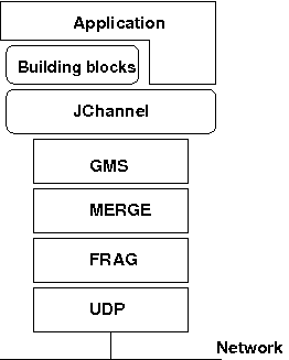
The architecture consists of
-
A JChannel used by application programmers to build reliable group communication applications
-
Building blocks, which are layered on top of the channel and provide a higher abstraction level
-
A protocol stack, which implements the properties specified for a given channel.
A channel is connected to a protocol stack. Whenever the application sends a message, the channel passes it on to the protocol stack, which passes it to the topmost protocol. The protocol processes the message and the passes it down to the protocol below it. Thus the message is handed from protocol to protocol until the bottom (transport) protocol puts it on the network.
The same happens in the reverse direction: the transport protocol listens for messages on the network. When a message is received, it will be handed up the protocol stack until it reaches the channel. The channel then invokes a callback in the application to deliver the message.
When an application connects to the channel, the protocol stack will be started, and when it disconnects, the stack will be stopped. When the channel is closed, the stack will be destroyed, releasing its resources.
The following sections discusses channels, building blocks and the protocol stack in more detail.
1.1. JChannel
To join a group and send messages, a process has to create a JChannel and connect to it using the group
name (all channels with the same name form a group).
The channel is the handle to the group.
While connected, a member may send and receive messages to/from all other group members.
A member leaves a group by disconnecting from the channel.
A channel can be reused: members can connect to it again after having disconnected themselves. However, a member can only be connected to one channel at any given time; in other words, a member can only join one cluster. It has to disconnect itself (= leave the cluster) in order to join a different cluster.
If multiple groups are to be joined, multiple channels have to be used. A member which no longer wants to use a channel can close it. After this operation, the channel cannot be used any longer.
Each channel has a unique address.
Channels always know who the other members are in the same group: a list of member addresses can be retrieved from a channel. This list is called a view. A process can select an address from the view and send a message to it, or it may send a multicast message to all members of the current view (including itself).
Whenever a process joins or leaves a group, or when a crashed process has been detected, a new view is sent to all existing (and new) members.
The protocols that a channel should create are typically defined in an XML file, but JGroups also allows for configuration of a protocol stack via URIs, DOM trees or even programmatically.
The JChannel API and its related classes is described in the API section.
1.2. Building Blocks
Channels are simple and primitive. They offer the bare functionality of group communication, and have been designed after the simple model of sockets, which are widely used and well understood. The reason is that an application can make use of just this small subset of JGroups, without having to include a whole set of sophisticated classes, that it may not even need. Also, a somewhat minimalistic interface is simple to understand: a client needs to know only a few methods (create, connect, send/receive, disconnect, close) to be able to use a channel.
Channels provide asynchronous message sending/reception. A message sent is essentially put on the network and the send will return immediately. Conceptual requests, or responses to previous requests, are received in undefined order, and the application has to take care of matching responses with requests.
JGroups offers building blocks that provide more sophisticated APIs on top of a JChannel. Building blocks either create and use channels internally, or require an existing channel to be specified when creating a building block.
Applications talk to the building block, rather than the channel. Building blocks are intended to save the application programmer from having to write tedious and recurring code, e.g. request-response correlation, and thus offer a higher level of abstraction to group communication.
Building blocks are described in Building Blocks.
1.3. The Protocol Stack
The protocol stack containins a number of protocols in a bidirectional list.
All messages sent and received over the channel have to pass through all protocols. Every layer may modify, reorder, pass or drop a message, or add a header.
For instance, a fragmentation layer might break up a message into several smaller messages, adding a header with an ID to each fragment, and re-assemble the fragments on the receiver’s side.
The composition of the protocol stack, i.e. its protocols, is determined by the creator of the channel: an XML file defines the protocols to be used (and the parameters for each protocol). The configuration is then used to create the stack.
Knowledge about the protocol stack is not necessary when only using channels in an application. However, when an application wishes to ignore the default properties for a protocol stack, and configure their own stack, then knowledge about what the individual layers are supposed to do is needed.
2. Installation and configuration
The installation refers to version 5.x of JGroups.
JGroups can be add to the POM:
<dependency>
  <groupId>org.jgroups</groupId>
  <artifactId>jgroups</artifactId>
  <version>5.0.0.Final</version>
</dependency>
Alternatively, the JAR can be downloaded from SourceForge.
It is named jgroups-x.y.z, where x=major, y=minor and z=patch version, for example jgroups-5.0.0.Final.jar.
The JAR is all that’s needed to get started using JGroups; it contains all core, demo and (selected) test classes, some sample XML configuration files and the XML schema.
The source code is hosted on GitHub. To build JGroups, ANT is currently used (but there’s also a POM for maven users).
In Building JGroups from source we’ll show how to build JGroups from source.
2.1. Requirements
-
3.6.x to (excluding) 4.0 requires JDK 7.
-
4.x requires JDK 8.
-
5.0.0.Final requires JDK 11 or higher
-
5.5.0 requires JDK 17 or higher
-
There is no JNI code present so JGroups runs on all platforms.
-
Logging: by default, JGroups tries to use log4j2. If the classes are not found on the classpath, it resorts to log4j, and if still not found, it falls back to JDK logging (
java.util.logging logger). See Logging for details on log configuration.
2.2. Structure of the source version
The source version consists of the following directories and files:
- src
-
the sources
- tests
-
unit and stress tests
- lib
-
JARs needed to either run the unit tests, or build the manual etc. No JARs from here are required at runtime! Note that these JARs are downloaded automatically via ivy. This directory is ignored if maven is used to build (artifacts are in
targetinstead). - conf
-
configuration files needed by JGroups, plus default protocol stack definitions
- doc
-
documentation
2.3. Building JGroups from source
-
Download the sources from GitHub, either via 'git clone', or the download link into a directory
JGroups, e.g./home/bela/JGroups. -
Download ant (preferably 1.10 or higher)
-
Change to the
JGroupsdirectory -
Run
ant -
This will compile all Java files (into the
classesdirectory). Note that if thelibdirectory doesn’t exist, ant will download ivy intoliband then use ivy to download the dependent libraries defined inivy.xml. -
To generate the JGroups JAR:
ant jar -
This will generate the following JAR files in the
distdirectory:-
jgroups-x.y.z.jar: the JGroups JAR -
jgroups-sources.jar: the source code for the core classes and demos
-
-
Now add the following directories to the classpath:
-
JGroups/classes -
JGroups/conf -
All needed JAR files in
JGroups/lib. Note that most JARs inlibare only required for running unit tests and generating test reports
-
-
To generate JavaDocs simple run:
ant javadocand the Javadoc documentation will be generated indist/javadoc
2.4. Logging
JGroups has no runtime dependencies; all that’s needed to use it is to have the jgroups.jar on the classpath.
For logging, this means the JVM’s logging (java.util.logging) is used.
However, JGroups can use any other logging framework. By default, log4j2 and slf4j are supported if the corresponding JARs are found on the classpath.
2.4.1. log4j2
To use log4j2, the API and CORE JARs have to be found on the
classpath. There’s an XML configuration for log4j2 in the conf dir, which can be used e.g. via
-Dlog4j.configurationFile=$JGROUPS/conf/log4j2.xml.
log4j2 is currently the preferred logging library used by JGroups, and will be used even if the log4j JAR is also present on the classpath.
2.4.2. log4j
To use log4j, the log4j JAR has to be found on the classpath. Note though that
if the log4j2 API and CORE JARs are found, then log4j2 will be used, so those JARs will have to be removed if log4j
is to be used. There’s an XML configuration for log4j in the conf dir, which can be used e.g. via
-Dlog4j.configuration=file:$JGROUPS/conf/log4j.properties.
2.4.3. JDK logging (JUL)
To force use of JDK logging, even if the log4j(2) JARs are present, -Djgroups.use.jdk_logger=true can be used.
2.4.4. Support for custom logging frameworks
JGroups allows custom loggers to be used instead of the ones supported by default. To do this, interface
CustomLogFactory has to be implemented:
public interface CustomLogFactory {
    Log getLog(Class clazz);
    Log getLog(String category);
}
The implementation needs to return an implementation of org.jgroups.logging.Log.
To use the custom log, LogFactory.setCustomLogFactory(CustomLogFactory f) needs to be called.
2.4.5. Setting the preferred log class
It is possible to set the preferred log class via system property jgroups.log_class. To do this, the fully
qualified name of a class which provides the following functionality has to be given:
-
Implement the
Loginterface -
Provide a constructor taking a
Classtype as only argument -
Provide a constructor taking a
Stringtype as only argument
Example: -Djgroups.log_class=org.jgroups.logging.Slf4jLogImpl
2.5. Testing your setup
To see whether your system can find the JGroups classes, execute the following command:
java org.jgroups.Version
or
java -jar jgroups-x.y.z.jar
You should see the following output (more or less) if the class is found:
$  java org.jgroups.Version

Version:      5.0.0.Final (Stelvio)
2.6. Running a demo program
To test whether JGroups works okay on your machine, run the following command twice:
java org.jgroups.demos.Draw
2 whiteboard windows should appear as shown in Screenshot of 2 Draw instances.
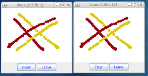
The (2) in the title means that the two instances found each other and formed a cluster.
When drawing in one window, the second instance should also be updated. As the default group transport uses IP multicast, make sure that - if you want start the 2 instances in different subnets - IP multicast is enabled. If this is not the case, the 2 instances won’t find each other and the example won’t work.
You can change the properties of the demo to for example use a different transport if multicast doesn’t work (it should always work on the same machine). Please consult the documentation for how to do this.
State transfer (see the section in the API later) can also be tested by passing the -state flag to Draw.
2.7. Using IP Multicasting without a network connection
Sometimes there isn’t a network connection (e.g. DSL modem is down), or we want to multicast only on the local machine. For this the loopback interface (typically lo) can be configured, e.g.
route add -net 224.0.0.0 netmask 240.0.0.0 dev lo
This means that all traffic directed to the 224.0.0.0 network will be sent to the loopback interface, which means it
doesn’t need any network to be running. Note that the 224.0.0.0 network is a placeholder for all multicast addresses
in most UNIX implementations: it will catch all multicast traffic.
The above instructions may also work for Windows systems, but this hasn’t been tested. Note that not all operating systems allow multicast traffic to use the loopback interface.
Typical home networks have a gateway/firewall with 2 NICs:
the first (e.g. eth0) is connected to the outside world (Internet Service Provider), the second (eth1) to the
internal network, with the gateway firewalling/masquerading traffic between the internal and external networks.
If no route for multicast traffic is added, the default will be to use the fdefault gateway, which will typically
direct the multicast traffic towards the ISP. To prevent this (e.g. ISP drops multicast traffic, or latency
is too high), we recommend to add a route for multicast traffic which goes to the internal network (e.g. eth1).
2.8. It doesn’t work!
Make sure your machine is set up correctly for IP multicasting. There is a test program mcast which can be used to
check if IP multicasting works.
The options are:
-bind_addr-
the network interface to bind to for the receiver. If null,
mcastwill join all available interfaces -port-
the local port to use. If 0, an ephemeral port will be picked
-mcast_addr-
the multicast address to join
-mcast_port-
the port to listen on for multicasts
-ttl-
The TTL (for sending of packets)
Start multiple instances of mcast:
java org.jgroups.tests.mcast
If you want to bind to a specific network interface card (NIC), use -bind_addr 192.168.0.2, where 192.168.0.2
is the IP address of the NIC to which you want to bind. Use this parameter in both sender and receiver.
You should be able to type in the mcast window and see the output in all other instance. If not, try to use -ttl 32
in the sender. If this still fails, consult a system administrator to help you setup IP multicast correctly. If you
are the system administrator, look for another job :-)
Other means of getting help: there is a public forum on JIRA for questions. Also consider subscribing to the javagroups-users mailing list to discuss such and other problems.
2.9. Problems with IPv6
Another source of problems might be the use of IPv6, and/or misconfiguration of /etc/hosts. If you communicate between
an IPv4 and an IPv6 host, and they are not able to find each other, try the -Djava.net.preferIPv4Stack=true
property, e.g.
java -Djava.net.preferIPv4Stack=true org.jgroups.demos.Draw -props /home/bela/udp.xml
The JDK uses IPv6 by default, although is has a dual stack, that is, it also supports IPv4.
To force use of IPv6, start your JVM with -Djava.net.preferIPv6Addresses=true.
2.10. I have discovered a bug!
If you think that you discovered a bug, submit a bug report on JIRA or send email to the jgroups-users mailing list if you’re unsure about it. Please include the following information:
-
✓ Version of JGroups (java org.jgroups.Version)
-
✓ Platform (e.g. Solaris 8)
-
❏ Version of JDK (e.g. JDK 1.6.20_52)
-
❏ Stack trace in case of a hang. Use kill -3 PID on UNIX systems or CTRL-BREAK on windows machines
-
✓ Small program that reproduces the bug (if it can be reproduced)
2.11. Supported classes
JGroups project has been around since 1998. Over this time, some of the JGroups classes have been used in experimental phases and have never been matured enough to be used in today’s production releases. However, they have not been removed, since some people use them in their products.
The following tables list unsupported and experimental classes. These classes are not actively maintained, and we will not work to resolve potential issues you might find. Their final fate is not yet determined; they might even be removed altogether in the next major release. Weight your risks if you decide to use them anyway.
2.11.1. Experimental classes
| Package | Class |
|---|---|
org.jgroups.blocks |
GridOutputStream |
org.jgroups.blocks |
GridInputStream |
org.jgroups.blocks |
GridFile |
org.jgroups.blocks |
GridFilesystem |
org.jgroups.auth |
Krb5Token |
org.jgroups.client |
StompConnection |
org.jgroups.protocols |
DAISYCHAIN |
org.jgroups.protocols |
BATCH2 |
org.jgroups.protocols |
SEQUENCER2 |
org.jgroups.protocols |
SWIFT_PING |
org.jgroups.protocols |
RATE_LIMITER |
org.jgroups.protocols |
SimpleTCP |
2.11.2. Unsupported classes
| Package | Class |
|---|---|
org.jgroups.blocks |
ReplicatedTree |
org.jgroups.protocols |
EXAMPLE |
org.jgroups.protocols |
DISCARD_PAYLOAD |
3. API
This chapter explains the classes available in JGroups that will be used by applications to build reliable group communication applications. The focus is on creating and using channels.
All of the classes discussed here are in the org.jgroups package unless otherwise mentioned.
3.1. Message
Data is sent between members in the form of messages. A message can be sent by a member to a single member, or to all members of the group.
The structure of a message is shown in Structure of a message.
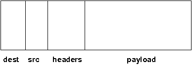
A message has the following fields:
- Destination address
-
The address of the receiver. If
null, the message will be sent to all current group members.Message.getDest()returns the destination address of a message. - Source address
-
The address of the sender. Can be
null, and will be filled in by the transport protocol (e.g. UDP) before the message is put on the network.Message.getSrc()returns the source address, ie. the address of the sender of a message. - Flags
-
Flags are used to override default behavior. For example, when setting the out-of-band flag
OOBin a message, the delivery order of it will get changed. For details, refer to section on message flags. - Headers
-
A list of headers that can be attached to a message. Anything that should not be in the payload can be attached to a message as a header. Methods
putHeader(),getHeader()andremoveHeader()ofMessagecan be used to manipulate headers.
Note that headers are mainly used by protocols. - Payload
-
The actual data (e.g. a byte array). The
Messageinterface contains convenience method definitions to set and get the different types of payloads, e.g. a byte array, an object, an NIOByteBufferand so on.
Payloads are defined by the different implementations ofMessage.
The Message interface is defined below (edited for legibility):
public interface Message extends SizeStreamable, Constructable<Message> {

    /** The type of the message */
    short BYTES_MSG=0, NIO_MSG=1, EMPTY_MSG=2, OBJ_MSG=3,
          COMPOSITE_MSG=5, FRAG_MSG=6, LONG_MSG=7;

    /** Returns the type of the message, e.g. BYTES_MSG, OBJ_MSG etc */
    short                 getType();

    /** Returns the destination address */
    Address               getDest();

    /** Sets the destination address */
    <T extends Message> T setDest(Address new_dest);

    /** Returns the address of the sender */
    Address               getSrc();

    /** Sets the address of the sender of this message */
    <T extends Message> T setSrc(Address new_src);

    /** Adds a header to the message */
    <T extends Message> T putHeader(short id, Header hdr);

    /** Gets a header from the message */
    <T extends Header> T  getHeader(short id);

    /** Sets one or more flags */
    <T extends Message> T setFlag(Flag... flags);

    /** Sets one or more transient flags */
    <T extends Message> T setFlag(TransientFlag... flags);

    /** Clears a number of flags */
    <T extends Message> T clearFlag(Flag... flags);

    /** Clears a number of transient flags */
    <T extends Message> T clearFlag(TransientFlag... flags);

    /** Returns true if a flag is set */
    boolean               isFlagSet(Flag flag);

    /** Returns true if a transient flag is set */
    boolean               isFlagSet(TransientFlag flag);

    /** Returns true if the message has a payload */
    boolean               hasPayload();

    /** Returns true if this message has a byte array as payload */
    boolean               hasArray();

    /**
     * Returns a reference to the payload (byte array). Throws an exception if
     * the message does not have a byte array payload (hasArray() is false).
     */
    byte[]                getArray();

    /** Returns the offset of the byte array at which user data starts.
     * Throws an exception if the message does not have a byte array payload.
     */
    int                   getOffset();

    /** Returns the length of the byte array payload. If the message does not
     * have a byte array payload, then the serialized size may be returned,
     * or an implementation may throw an exception */
    int                   getLength();

    /**
     * Sets the byte array in a message. Throws an exception if the
     * message does not have a byte array payload.
     */
    <T extends Message> T setArray(byte[] b, int offset, int length);

    /**
     * Sets the byte array in a message. Throws an exception if the message
     * does not have a byte array payload.
     */
    <T extends Message> T setArray(ByteArray buf);

    /**
     * Gets an object from the payload. If the payload is a byte array,
     * an attempt to de-serialize the array into an object is made, and
     * the object returned. If the payload is an object (e.g. as in
     * an ObjectMessage), the object will be returned directly.
     */
    <T extends Object> T  getObject();

    /**
     * Sets an object in a message. In a ObjectMessage, the object is
     * set directly.
     * In a BytesMessage, the object is serialized into a byte array
     * and set as the payload of the message.
     */
    <T extends Message> T setObject(Object obj);

    /**
     * Returns the payload without any conversion (e.g. as in {@link #getObject()} or {@link #getArray()})
     */
     <T extends Object> T getPayload();

     /**
      * Sets the payload
      * @param pl The paylolad
      */
     Message              setPayload(Object pl);


    /** Returns the exact size of the marshalled message */
    int                   size();

    enum Flag {
        OOB,            // message is out-of-band
        DONT_BUNDLE,    // don't bundle message at the transport
        NO_FC,          // bypass flow control
        NO_RELIABILITY, // bypass UNICAST3 and NAKACK2
        NO_TOTAL_ORDER, // bypass total order (e.g. SEQUENCER)
        NO_RELAY,       // bypass relaying (RELAY2)
        RSVP,           // ack of a multicast
        RSVP_NB,        // non blocking RSVP
        SKIP_BARRIER;   // passing messages through a closed BARRIER
    }

    enum TransientFlag {
        OOB_DELIVERED,
        DONT_LOOPBACK;   // don't loopback if set and a multicast message
    }
}
Message defines methods to get and set the destination and sender’s address, set/clear flags and add and remove
headers. These methods are implemented in BaseMessage, which is extended by all message implementations.
The rest of the methods are defined to get and set the payload. They’re all generic, and implementations may or may not choose to implement them.
The table below describes the payload-related methods of Message:
| Name | Description |
|---|---|
hasPayload |
Returns true if the message has a payload, e.g. a byte array or an object.
This is more generic than |
hasArray |
Returns true if the payload is a byte array (even if it’s null). |
getArray |
Returns a reference to the byte array (if the payload is a byte array). May throw an exception
if the payload is not a byte array ( |
getOffset |
Returns the offset of the payload in the byte array. |
getLength |
Returns the length of the payload. |
setArray |
Sets the byte array in a message. Throws an exception if the message does not have a byte array payload (hasArray() is false). |
getObject |
Gets an object from the payload. If the payload is a byte array, an attempt to de-serialize
the array into an object is made, and the object returned. |
setObject |
Sets an object in a message. In a |
getPayload |
Gets the payload from a message. The actual payload without any conversions is returned. E.g. compared
to |
setPayload |
Sets the payload |
3.2. Message types
The Message interface has a number of subclasses, each having a different payload. BytesMessage
for example can be used with byte arrays, NioMessage handles ByteBuffer types and
ObjectMessage accepts (serializable) Objects as payload.
A second set of message types operates on other messages and does not provide a payload of its own:
FragmentedMessage wraps any other message that’s too big to be sent by the transport (e.g.
UDP has a datagram size limit of ~65K) with a fragmentation size, and creates fragments of the underlying message
when sent. On the receiver side, the fragments are cached and the original message is re-created when all fragments
have been received and then sent up.
CompositeMessage wraps multiple messages and marshals them at send time. For example, if the
application has an NIO ByteBuffer and a 4-byte command (byte array), then rather than creating a byte array, copying
the command and the ByteBuffer into it, and passing the resulting byte array to the message in 4.x, in 5.0 the
application can simply create a CompositeMessage and pass the command and ByteBuffer to it, and the
CompositeMessage will marshal both at send time.
The available message types are discussed below.
3.2.1. Late marshalling
Contrary to JGroups 4.x, the Message subclasses perform late marshalling: rather than having to marshal an object
into a byte array (to be passed to a 4.x Message), the object in the payload of an ObjectMessage is serialized
at send time only, possibly directly into a network socket’s buffer (or output stream).
The following example shows 4.x code:
MyObject obj=...;
byte[] buffer=Util.objectToByteBuffer(obj); // memory allocation
Message msg=new Message(null, buffer);
channel.send(msg);
The object is serialized into a byte array, which is passed to the Message constructor. At the network level, that
byte array will get written to the output stream of the socket. The buffer byte array is a temporary copy, and
introduces additional memory allocation.
In 5.0, we can eliminate the allocation:
MyObject obj=...;
Message msg=new ObjectMessage(null, obj);
channel.send(msg);
The ObjectMessage type does not serialize the object until the message itself is serialized (at send time). The
entire message including the object payload is written directly to the socket’s output stream.
The elimination of memory allocation for those temporary byte arrays reduces overall memory pressure, possibly leading
to better performance.
3.2.2. MessageFactory
JGroups 5.0 comes with a number of message types (see the next sections). If none of them are a fit for the application’s
requirements, new message types can be defined and registered. To do this, the new message type needs to implement
Message (typically by subclassing BaseMessage) and registering it with the MessageFactory:
CustomMessage msg=new CustomMessage(...);
MessageFactory.register((short)12345, CustomMessage::new)
A (unique) ID has to be assigned with the message type, and then it has to be registered with the message factory
in the transport. This has to be done before sending an instance of the new message type.
If the ID has already been registered before, or is taken, an exception will be thrown.
MessageFactory requires all IDs to be greater than 32, so that there’s room for adding built-in message types.
|
|
It is recommended to register all custom message types before connecting the channel, so that potential errors are detected early. |
3.2.3. BytesMessage
This is the equivalent to the 4.x Message, and contains a byte array, offset and length. There are methods to get and
set the byte array from a byte array, NIO ByteBuffer, Object etc. The latter case marshals the object into a byte
array and sets it in the message. Conversely, getObject() tries to unmarshal the byte array into an object.
|
|
It is recommended to only use the methods which get and set a byte array, as the other methods may get deprecated in the future. See the section on payload mismatch below for details. |
The simplest way to convert 4.x applications to 5.0 is:
Message msg=new Message(null, "hello world".getBytes()); // 4.xMessage msg=new BytesMessage(null, "hello world".getBytes()); // 5.03.2.4. NioMessage
An NioMessage has a ByteBuffer as payload. The ByteBuffer can be heap-based or direct (off-heap). A heap-based
buffer will be created with heap memory again when received. For an off-heap (direct) buffer, we can choose whether
heap memory should be used for the buffer when receiving an NioMessage, or whether off-heap (direct) memory should
be used. See the useDirectMemory() method below.
Alternatively, a custom message factory could manage a pool of off-heap memory and create the buffer in the
NioMessage with memory from that pool.
The methods of NioMessage are:
| Name | Description |
|---|---|
isDirect() |
Returns true if the buffer is off-heap, false otherwise |
getBuf() |
Returns the |
setBuf(ByteBuffer) |
Sets the |
useDirectMemory() |
When true, the |
useDirectMemory(boolean b) |
If true, use direct memory when creating |
|
|
The envisioned use case for useDirectMemory() is when we send an NioMessage with a direct ByteBuffer, but
don’t need the ByteBuffer to be created in off-heap memory at the receiver, when on-heap will do.
|
3.2.5. EmptyMessage
As its name implies, an EmptyMessage carries no payload. This means that it uses less memory, e.g. compared to
BytesMessage, it has 3 fields (array, offset, length) less, and so has ~12 bytes less.
JGroups itself uses quite some messages that send around no payload, only headers, and EmptyMessage instances are
ideal for this.
Here’s an example that sends a heartbeat in FD_ALL:
Message heartbeat=new EmptyMessage()
                   .setFlag(Message.Flag.OOB)
                   .putHeader(id, new HeartbeatHeader());
While this message type is mainly used internally, it is a public class and can as such be used by applications, too.
3.2.6. ObjectMessage
An ObjectMessage has a Plain Old Java Object (POJO) as payload. The object payload is marshalled directly into the
output stream at send time, using writeTo().
If the object implements SizeStreamable, then the writeTo() and readFrom() methods will be used for efficient,
application-controlled, marshalling. Otherwise, for some object types ('primitive types such as int, Boolean,
byte[] etc), JGroups will try to do the marshalling.
For all other cases, the the object is wrapped into an ObjectWrapper which uses just-in-time serialization to generate
a byte array, which is later written to the output stream.
|
|
When the byte array is set, the contents of the object should not be changed anymore, or else the old state
of the object will be sent on serialization. In case the object needs to be changed nevertheless, then
method setObject(Object) can be used: it will set the object and null the serialized format byte array, so
at marshalling time, it will be set again.
|
To get and set the payload, methods getObject() and setObject() should be used. Methods getArray() /
setArray() will throw an exception.
Sample code:
Message msg=new ObjectMessage(null, obj);           // constructor
Message msg=new ObjectMessage(null).setObject(obj); // setter
MyObject obj=msg.getObject();
3.2.7. LongMessage
A LongMessage has a long as payload. This allows for simple sending of longs and integers, without having
to marshal them into byte arrays.
These types are used for example in the flow control protocols to send credit-requests and responses.
3.2.8. CompositeMessage
This message type has multiple messages as payload. The messages have to have the same destination.
It solves the following problem (4.x code):
final String hello="hello world";
byte[] metadata=createMetadata();                 // metadata
ByteBuffer cmd=ByteBuffer.wrap(hello.getBytes()); // the command

byte[] arr=new byte[metadata.length + cmd.remaining()];  // temp memory allocation!
System.arraycopy(metadata, 0, arr, 0, metadata.length);
System.arraycopy(cmd.array(), cmd.arrayOffset(), arr, metadata.length, cmd.remaining());
Message msg=new Message(null, arr);
// send the message consisting of metadata and command

public void receive(Message msg) {
    byte[] array=msg.getRawBuffer(), metadata=new byte[4];
    int offset=msg.getOffset(), len=msg.getLength();

    System.arraycopy(array, offset, metadata, 0, metadata.length);
    ByteBuffer cmd=ByteBuffer.allocate(hello.length);
    cmd.put(array, metadata.length, len-metadata.length);
    // process metadata and command
}
In the above code, we have to create a new byte array and copy the metadata and command into it. Then a message with the combined data is sent. At the receiver, we have to divide the combined byte array into the metadata and command portions again.
This code can be rewritten using CompositeMessage as follows (5.0 code):
final String hello="hello world";

byte[] metadata=createMetadata();
ByteBuffer cmd=ByteBuffer.wrap(hello.getBytes());

Message msg=new CompositeMessage(null, new BytesMessage(null, metadata),
                                       new NioMessage(null, cmd));
// send the message with metadata and command

public void receive(Message msg) {
    CompositeMessage cm=(CompositeMessage)msg;
    BytesMessage m1=cm.get(0);
    NioMessage m2=cm.get(1);
    // process metadata (m1) and command (m2)
}
Here, we don’t have to combine the two pieces of data into one, but simply pass them to a CompositeMessage, which
is then sent. At the receiver, the received Message is narrowed to a CompositeMessage and the individual messages
can simply be accessed by index.
This eliminates 1 memory allocation, and it also simplifies programming a bit.
The methods of CompositeMessage are:
| Name | Description |
|---|---|
getNumberOfMessages() |
Returns the number of messages |
add(Message) |
Adds a message, increasing the capacity if needed |
add(Message … msgs) |
Adds a number of messages |
get(int index) |
Returns the message at the given index |
collapse(boolean) |
Collapses the payload and sends the message as a |
For a detailed listing of all methods consult the javadoc.
Collapsing a CompositeMessage
When we send a CompositeMessage consisting of a BytesMessage of 1000 bytes and an NioMessage of 50 bytes,
we may want to receive a BytesMessage of 1050 bytes, with the payloads of the individual messages
collapsed, rather than a CompositeMessage.
This is oftentimes the case when we would like to combine the 2 payloads at the sender side into 1, but want to avoid the overhead of the byte array creation of size 1050, but don’t mind handling the full 1050-byte array at the receiver side.
The code below shows how to use collapse():
public void testCollapse2() throws Exception {
    CompositeMessage msg=new CompositeMessage(DEST)
        .add(new BytesMessage(DEST, "hello".getBytes()))
        .add(new NioMessage(DEST, ByteBuffer.wrap(" world".getBytes())))
        .add(new ObjectMessage(DEST, "hello"))
        .collapse(true);
    int length=msg.getLength();
    ByteArray buf=Util.messageToBuffer(msg);
    Message msg2=Util.messageFromBuffer(buf.getArray(),
                                        buf.getOffset(),
                                        buf.getLength(), MF);
    assert msg2 instanceof BytesMessage;
    assert msg2.getLength() == length;

    byte[] bytes=msg2.getArray();
    String s=new String(bytes, 0, 11);
    assert s.equals("hello world");
    DataInput in=new ByteArrayDataInputStream(bytes,
                                              s.length(),
                                              bytes.length-s.length());
    ObjectMessage om=new ObjectMessage();
    om.readPayload(in);
    assert om.getObject() instanceof String;
    assert om.getObject().equals("hello");
}
Here, we’re adding a byte array, an NIO ByteBuffer and an object and then set collapse() in the
CompositeMessage.
This means that - at serialization time - the byte array is written first (without the size), then the
ByteBuffer, then the object.
When receiving the message, we see that it’s a BytesMessage, not a CompositeMessage. We know that the
payloads of the BytesMessage ("hello") and the payload of the NioMessage (" world") have been combined
and can therefore read the entire 11 bytes directly into a string "hello world".
After this, we read the object (via an ObjectMessage).
|
|
Payload collapsing is envisaged to be used mainly for message types which have an array (e.g. BytesMessage
or NioMessage).
|
3.2.9. FragmentedMessage
A FragmentedMessage wraps another message (also a CompositeMessage!), with an offset and length. The offset/length
combo defines a subrange of the underlying message that is to be marshalled.
For example, if we have an ObjectMessage whose length is 500, and the fragmentation size is 200, then 3
FragmentedMessage instances will be created, with ranges 0..199, 200..399 and 400..499.
The second FragmentedMessage will only marshall the part of the underlying message between indices 200 and 399.
FragmentedMessage is only used internally by the fragmentation protocols, and not by users. It is discussed here
mainly for completeness.
3.2.10. Reference-counted messages
When a sender wants to reuse the message payload, a shared pool of payloads may be used. For example, we may want to create a pool of direct ByteBuffers (allocated off-heap) and wrap ByteBuffers (taken from that pool) in NioMessages.
After sending an NioMessage with ByteBuffer buf, we may want to modify buf and send another NioMessage with buf
as payload. However, this might fail, as the message may not yet have been sent, or it may have been dropped and
will later get retransmitted.
For example, if we set buf to 123, send it, then set it to 456 and send it again, the following
might happen:
-
123is sent as NioMessagem1, butm1is dropped -
456is sent as NioMessagem2 -
m1gets retransmitted. By now, its payload is456, asbufhas been changed in the meantime -
This leads to a receiver receiving
456twice, rather than123followed by456.
Reference counting makes sure that a payload is only available to be reused when
-
a unicast message has been sent to a receiver and the ack from the receiver has been received by the sender, so that the message can be purged from the retransmission table, or
-
a multicast message (= message to all members) has been seen by all members and has been purged from the retransmission table.
This is achieved by reference counting: a message increments a reference count (refcnt) when being sent,
and decrements it when JChannel.send() returns. Retransmission protocols (such as NAKACK2 or UNICAST3)
increment refcnt, and decrement it when the message is known to have been received by the receiver(s).
For a unicast message M to a member P, removal of M from the retransmission table typically happens when an ACK (sent by P) for M has been received.
For a multicast message M sent to all members, removal happens when STABLE purges M from the retransmission table
when all members have seen M.
When refcnt becomes 0, a callback is invoked (with the message as argument), which can (e.g.) return the message to a pool.
As example of a refcounted message is RefcountedNioMessage:
public class RefcountedNioMessage extends NioMessage implements Refcountable<Message> {
    protected final RefcountImpl<Message> impl=new RefcountImpl<>();

    public RefcountedNioMessage() {
    }

    public RefcountedNioMessage(Address dest) {
        super(dest);
    }

    public RefcountedNioMessage(Address dest, ByteBuffer buf) {
        super(dest, buf);
    }

    public synchronized byte getRefcount() {
        return impl.getRefcount();
    }

    @Override public synchronized RefcountedNioMessage incr() {
        impl.incr();
        return this;
    }

    @Override public synchronized RefcountedNioMessage decr() {
        impl.decr(this);
        return this;
    }

    public RefcountedNioMessage onRelease(Consumer<Message> rc) {
        impl.onRelease(rc);
        return this;
    }
}
It subclasses NioMessage and implements methods incr() and decr() of the Refcountable interface. The latter calls
a function previously passed in via onRelease(). This function may for example return the payload of the NioMessage
to a pool. See RefcountedNioMessageTest as an example.
|
|
Reference counting is an experimental feature, introduced in 5.1.0 (and again in 5.5.1), and is WIP. The authors are interested in scenarios where this would be beneficial, and its performance impact. Please contact us if you are serious about using this feature; we’re interested in feedback, suggestions and are happy to collaborate on this! |
Reference counting on the receiver side
Reference counting is currently only implemented on the sender side.
However, it could also be useful on the receiver side: a MessageFactory could create instances of ref-counted messages
(the payload would be taken from a buffer pool) and increment the refcount.
When such a message is received and processed by the application, the receive(Message) callback (or, alternatively,
the application itself) could decrement the refcount, thus returning the buffer to the pool.
3.3. Mismatch between message type and getters/setters
The Message interface has a number of generic methods to get/set payloads of various types.
It makes sense to call getArray() / setArray() on a BytesMessage and getObject() / setObject() on an
ObjectMessage.
However, there are mismatches between message type and getters / setters:
-
BytesMessageandgetObject(): the byte array payload will need to be de-serialized into an object. This is slower than using anObjectMessageinstead and callinggetObject()on it to get the object.
If an object needs to be serialized into a byte array and we want to use aBytesMessage, then it is better if the application serializes the object and passes the byte array to theBytesMessage, rather than JGroups doing the serialization: the application has more knowledge of its types and can therefore do a much better job at serialization than the generic algorithm used by JGroups. -
CompositeMessageandgetArray()/getObject(): this will throw an exception -
NioMessageandgetArray(): this works, but will create a new byte array (unneeded memory allocation)
In these cases, it makes sense to narrow the Message to its actual type and use the subclass:
public void receive(Message msg) {
    NioMessage m=(NioMessage)msg;
    ByteBuffer buf=m.getBuf();
    // do something directly with the ByteBuffer
}
After all, the application knows what message types it sends, and can therefore safely downcast.
3.4. Receiver
The Receiver interface defines the callbacks that are invoked at the receiver side:
public interface Receiver {

    default void receive(Message msg) {
    }

    default void receive(MessageBatch batch) {
        for(Message msg: batch) {
            try {
                receive(msg);
            }
            catch(Throwable t) {
            }
        }
    }

    default void viewAccepted(View new_view) {}

    default void block() {}

    default void unblock() {}

    default void getState(OutputStream output) throws Exception {
        throw new UnsupportedOperationException();
    }

    default void setState(InputStream input) throws Exception {
        throw new UnsupportedOperationException();
    }
}| Name | Description |
|---|---|
receive(Message) |
A message is recived |
receive(MessageBatch) |
A message batch is received |
viewAccepted |
Called when a change in membership has occurred. No long running actions, sending of messages or anything that could block should be done in this callback. If some long running action needs to be performed, it should be done in a separate thread. |
getState |
Allows an application to write the state to an OutputStream. After the state has been written, the OutputStream doesn’t need to be closed as stream closing is automatically done when a calling thread returns from this callback. |
setState |
Allows an application to read the state from an InputStream. After the state has been read, the InputStream
doesn’t need to be closed as stream closing is automatically done when a calling thread
returns from this callback. |
|
|
Note that anything that could block should not be done in a callback. This includes sending of messages; If we need to send a message in a callback, the sending should be done on a separate thread, or a task should be submitted to the timer. |
A Receiver callback is registered with the channels via JChannel.setReceiver(Receiver).
3.4.1. ChannelListener
public interface ChannelListener {
    void channelConnected(JChannel channel);
    void channelDisconnected(JChannel channel);
    void channelClosed(JChannel channel);
}
A class implementing ChannelListener can use the JChannel.addChannelListener() method to register with a channel to obtain information about state changes in a channel. Whenever a channel is closed, disconnected or opened, the corresponding callback will be invoked.
3.5. Address
Each member of a group has an address, which uniquely identifies the member. The interface for such an
address is Address, which requires concrete implementations to provide methods such as comparison and
sorting of addresses. JGroups addresses have to implement the following interface:
public interface Address extends Streamable, Comparable<Address> {
    int size();
}
For marshalling purposes, size() needs to return the number of bytes an instance of an address implementation
takes up in serialized form.
|
|
Please never use implementations of Address directly; Address should always be used as an opaque identifier of a cluster node! |
Actual implementations of addresses are generated by the transport protocol (e.g. UDP or TCP).
This allows for all possible types of addresses to be used with JGroups.
Since an address uniquely identifies a channel, and therefore a group member, it can be used to send messages to that group member, e.g. in Messages (see next section).
The default implementation of Address is org.jgroups.util.UUID. It uniquely identifies
a node, and when disconnecting and reconnecting to a cluster, a node is given a new UUID on reconnection.
UUIDs are never shown directly, but are usually shown as a logical name (see Logical names). This is a name given to a node either via the user or via JGroups, and its sole purpose is to make logging output a bit more readable.
UUIDs maps to IpAddresses, which are IP addresses and ports. These are eventually used by the transport protocol to send a message.
3.6. MessageBatch
A message batch is a class used to deliver messages which includes a number of messages rather than just one. The sender and destination (= receiver) of a batch is the same for all messages of the batch. A batch can be iterated over, e.g.
MessageBatch batch;
for(Message msg: batch) {
    // do something with msg
}
The advantage of a message batch is that multiple messages are delivered in one go; which means potential locks are acquired only once, we have fewer threads (less work for the thread pool) and fewer context switches.
JGroups tries to bundle as many messages as possible into a batch on the sender side.
Also on the receiver side, if multiple threads added messages to a table, it tries to remove as many of them as possible and pass them up to other protocols (or the application) as a batch.
3.6.1. Cost of processing of message batches
A message batch is delivered to the application via the receive(MessageBatch) callback. While each message of
an OOB batch could be delivered in a separate thread, regular messages need to be delivered one by one, or else
ordering will be destroyed.
If the average processing time for a message is 20us, in a batch of 10 it will take 20us to process the first
message, 40us to process the second and so on. The last message is delayed by 180us before it can be processed.
For latency-sensitive applications, batching is detrimental to performance. There are a few things to fix this:
-
Make smaller batches on the sender side: reduce
max_bundle_size. However, aMessageProcessingPolicy(Message processing policy) ofmaxwill still create larger batches on the receiver side. A smallermax_bundle_sizeleads only to faster filling and sending of batches on the sender side. This still helps latency. -
Use a
MessageProcessingPolicyofunbatch: this delivers only OOB batches up to a given size; larger batches deliver their messages in separate threads. -
Application: an application knows best whether messages in a batch can be processed in parallel, or whether they need to be delivered sequentially. Example: responses in a batch could be delivered each by a separate thread, whereas requests would need to be processed sequentially.
3.7. Header
A header is a custom bit of information that can be added to each message. JGroups uses headers extensively, for example to add sequence numbers to each message (NAKACK and UNICAST), so that those messages can be delivered in the order in which they were sent.
3.8. Event
Events are means by which JGroups protcols can talk to each other. Contrary to Messages, which travel over the network between group members, events only travel up and down the stack.
|
|
Headers and events are only used by protocol implementers; they are not needed by application code! |
3.9. View
A view (org.jgroups.View) is a list of the current members of a group. It consists
of a ViewId, which uniquely identifies the view (see below), and a list of members.
Views are installed in a channel automatically by the underlying protocol stack whenever a new member joins
or an existing one leaves (or crashes). All members of a group see the same sequence of views.
Note that the first member of a view is the coordinator (the one who emits new views). Thus, whenever the membership changes, every member can determine the coordinator easily and without having to contact other members, by picking the first member of a view.
The code below shows how to send a (unicast) message to the first member of a view (error checking code omitted):
View view=channel.getView();
Address first=view.getMembers().get(0);
Message msg=new ObjectMessage(first, "Hello world");
channel.send(msg);
Whenever an application is notified that a new view has been installed (e.g. by
Receiver.viewAccepted(), the view is already set in the channel. For example,
calling Channel.getView() in a viewAccepted()
callback would return the same view (or possibly the next one in case there has already been a new view!).
3.9.1. ViewId
The ViewId is used to uniquely number views. It consists of the address of the view creator and a
sequence number. ViewIds can be compared for equality and put in a hashmaps as they implement equals()
and hashCode().
|
|
Note that the latter 2 methods only take the ID into account. |
3.9.2. MergeView
Whenever a group splits into subgroups, e.g. due to a network partition, and later the subgroups merge
back together, a MergeView instead of a View will be received by the application. MergeView is
a subclass of View and contains as additional instance variables the list of views that were merged.
As an example if the cluster with view V1={P,Q,R,S,T} split into subgroups V2={P,Q,R} and V2={S,T}, the merged view might be V3={P,Q,R,S,T}. In this case the MergeView contains a list of two views: V2={P,Q,R}) and V2={S,T}.
|
|
Because the default merge policy adds members from subgroups into a common group and sorts the resulting list, the membership order might change on a merge event. Thus a view V1={P,Q,R,S,T}, followed by view V2={P,Q,R} and V2={S,T} might result in a merge view V3={P,T,Q,S,R}. To prevent this, the task of creating new views can be delegated to custom code (see Determining the coordinator and controlling view generation). |
|
|
Because merging needs to handle all edge cases, it is not guaranteed that subsequent MergeViews won’t have identical membership. For example, we we have view A2={A,B} in A and B3={B} in B, then a subsequent merge might install view A4={A,B} in both A and B. In A’s case, the membership between A2 and A4 doesn’t change. An application has to be able to handle duplicate subsequent merge views. Note that consecutive regular views will never have duplicate members. |
3.10. JChannel
In order to join a group and send messages, a process has to create a channel. A channel is like a socket. When a client connects to a channel, it gives the the name of the group it would like to join. Thus, a channel is (in its connected state) always associated with a particular group. The protocol stack takes care that channels with the same group name find each other: whenever a client connects to a channel given group name G, then it tries to find existing channels with the same name, and joins them, resulting in a new view being installed (which contains the new member). If no members exist, a new group will be created.
A state transition diagram for the major states a channel can assume are shown in [ChannelStatesFig].
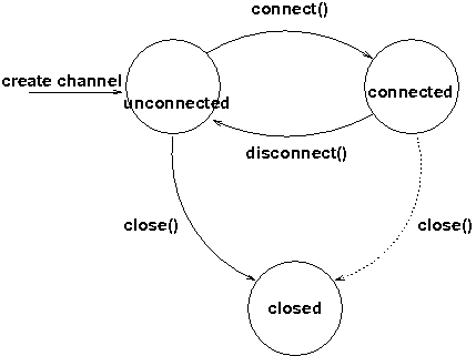
When a channel is first created, it is in the unconnected state.
An attempt to perform certain operations which are only valid in the connected state (e.g. send/receive messages) will result in an exception.
After a successful connection by a client, it moves to the connected state. Now the channel will receive messages from other members and may send messages to other members or to the group, and it will get notified when new members join or leave. Getting the local address of a channel is guaranteed to be a valid operation in this state (see below).
When the channel is disconnected, it moves back to the unconnected state. Both a connected and unconnected channel may be closed, which makes the channel unusable for further operations. Any attempt to do so will result in an exception. When a channel is closed directly from a connected state, it will first be disconnected, and then closed.
The methods available for creating and manipulating channels are discussed now.
3.10.1. Creating a channel
A channel is created using one of its public constructors (e.g. new JChannel()).
The most frequently used constructor of JChannel looks as follows:
public JChannel(String props) throws Exception;The props argument points to an XML file containing the configuration of the protocol stack to be used. This can be a String, but there are also other constructors which take for example a DOM element or a URL (see the javadoc for details).
The code sample below shows how to create a channel based on an XML configuration file:
JChannel ch=new JChannel("/home/bela/udp.xml");If the props argument is null, the default properties will be used. An exception will be thrown if the channel cannot be created. Possible causes include protocols that were specified in the property argument, but were not found, or wrong parameters to protocols.
For example, the Draw demo can be launched as follows:
java org.jgroups.demos.Draw -props file:/home/bela/udp.xml
or
java org.jgroups.demos.Draw -props http://www.jgroups.org/udp.xml
In the latter case, an application downloads its protocol stack specification from a server, which allows for central administration of application properties.
3.10.2. Configuration
A sample XML configuration looks like this (edited from udp.xml):
<config xmlns="urn:org:jgroups"
        xmlns:xsi="http://www.w3.org/2001/XMLSchema-instance"
        xsi:schemaLocation="urn:org:jgroups http://www.jgroups.org/schema/jgroups.xsd">
    <UDP
         mcast_port="${jgroups.udp.mcast_port:45588}"
         ip_ttl="4"
         bundler.max_size="64K"
         diag.enabled="true"
         thread_pool.min_threads="2"
         thread_pool.max_threads="8"
         thread_pool.keep_alive_time="5000" />
    <PING />
    <MERGE3 max_interval="30000" min_interval="10000"/>
    <FD_SOCK/>
    <FD_ALL/>
    <VERIFY_SUSPECT timeout="1500"  />
    <pbcast.NAKACK2 xmit_interval="500" />
    <UNICAST3 xmit_interval="500" />
    <pbcast.STABLE desired_avg_gossip="50000"
                   max_bytes="4M"/>
    <pbcast.GMS print_local_addr="true" join_timeout="2000"/>
    <UFC max_credits="2M"
         min_threshold="0.4"/>
    <MFC max_credits="2M"
         min_threshold="0.4"/>
    <FRAG2 frag_size="60K"  />
</config>
A stack is wrapped by <config> and </config> elements and lists all protocols from bottom
(UDP) to top (FRAG2). Each element defines one protocol.
Each protocol is implemented as a Java class. When a protocol stack is created based on the above XML configuration, the first element ("UDP") becomes the bottom-most layer, the second one will be placed on the first, etc: the stack is created from the bottom to the top.
Each element has to be the name of a Java class that resides in the org.jgroups.protocols package.
Note that only the base name has to be given, not the fully specified class name
(UDP instead of org.jgroups.protocols.UDP).
If the protocol class is not found, JGroups assumes that the name given is a fully qualified classname
and will therefore try to instantiate that class. If this does not work an exception is thrown.
This allows for protocol classes to reside in different packages altogether, e.g. a valid protocol name
could be com.sun.eng.protocols.reliable.UCAST.
Each layer may have zero or more arguments, which are specified as a list of name/value pairs in
parentheses directly after the protocol name. In the example above, UDP is configured with some options,
one of them being the IP multicast port (mcast_port) which is set to 45588, or to the value of
the system property jgroups.udp.mcast_port, if set.
|
|
Note that all members in a group have to have the same protocol stack. |
Using includes
Oftentimes different configurations have parts in common which change, but the rest is the same. An example of the
latter is transports such as TCP or UDP. These could be defined once, and be included by various
configurations. For example, if we have optimized transport configurations tcp-default.xml (TCP) and
nio-default.xml (TCP_NIO2), we could include them as follows:
<config>
   <include file="${transport-config:tcp-default.xml}" />
   <MPING />
   <MERGE3 max_interval="30000"
           min_interval="${min:10000}"/>
   ...
</config>
This configuration by default includes the transport defined in tcp-default.xml. All the configurations which
include this transport configuration will benefit from changes made to tcp-default.xml, which is better than
copy-and-paste where there’s a risk to forget to update all configurations.
Note that we can pick the transport to be included at run time, by defining system (or environment) variable
transport-config in the example above:
-
-Dtransport-config=tcp-default.xmluses aTCPtransport -
-Dtransport-config=nio-default.xmlusesTCP_NIO2as transport
Includes allow us to override attributes:
  <include file="${transport-config:/Users/bela/tcp-default.xml}"
           bundler.use_single_sender_thread="false"
           sock_conn_timeout="${conn-timeout:500}" />
This includes a file tcp-default.xml, but overrides (or adds) attributes bundler.use_single_sender_thread and
sock_conn_timeout.
We can also use multiple includes in the same configuration, e.g.:
<config>
   <include file="${transport-config:tcp-default.xml}" />
   <include file="${discovery-config:mping-default.xml}" />
   <MERGE3 max_interval="30000"
           min_interval="${min:10000}"/>
   ...
</config>
This includes a transport, but also the discovery protocol to be used, in 2 separate includes. This allows us to tailor the stack to be run to the environment.
To summarize: includes allow us to remove a lot of boilerplate code and customize the stack to the environment, even at run time.
|
|
includes were added in 5.5.0; prior versions will not recognize them and fail at startup |
Programmatic creation
Usually, channels are created by passing the name of an XML configuration file to the JChannel() constructor. On top of this declarative configuration, JGroups provides an API to create a channel programmatically.
The way to do this is to first create a JChannel, then an instance of
ProtocolStack, then add all desired protocols to the stack and finally calling init() on the stack
to set it up. The rest, e.g. calling JChannel.connect() is the same as with the declarative
creation.
An example of how to programmatically create a channel is shown below (copied from ProgrammaticChat):
public class ProgrammaticChat {
public static void main(String[] args) throws Exception {
Protocol[] prot_stack={
new UDP().setValue("bind_addr", InetAddress.getByName("127.0.0.1")),  new PING(),
new MERGE3(),
new FD_SOCK(),
new FD_ALL(),
new VERIFY_SUSPECT(),
new BARRIER(),
new NAKACK2(),
new UNICAST3(),
new STABLE(),
new GMS(),
new UFC(),
new MFC(),
new FRAG2()};
JChannel ch=new JChannel(prot_stack).name(args[0]);
new PING(),
new MERGE3(),
new FD_SOCK(),
new FD_ALL(),
new VERIFY_SUSPECT(),
new BARRIER(),
new NAKACK2(),
new UNICAST3(),
new STABLE(),
new GMS(),
new UFC(),
new MFC(),
new FRAG2()};
JChannel ch=new JChannel(prot_stack).name(args[0]);  ch.setReceiver(new ReceiverAdapter() {
public void viewAccepted(View new_view) {
System.out.println("view: " + new_view);
}
public void receive(Message msg) {
System.out.println("<< " + msg.getObject() + " [" + msg.getSrc() + "]");
}
});
ch.connect("ChatCluster");
for(;;) {
String line=Util.readStringFromStdin(": ");
ch.send(null, line); // causes an ObjectMessage to be created
}
}
}
ch.setReceiver(new ReceiverAdapter() {
public void viewAccepted(View new_view) {
System.out.println("view: " + new_view);
}
public void receive(Message msg) {
System.out.println("<< " + msg.getObject() + " [" + msg.getSrc() + "]");
}
});
ch.connect("ChatCluster");
for(;;) {
String line=Util.readStringFromStdin(": ");
ch.send(null, line); // causes an ObjectMessage to be created
}
}
}First, the JChannel is created (1) with an array of protocols. The protocols have some fields already set, e.g.
bind_addr in UDP (2).
The protocols are arranged bottom-first; e.g. UDP as transport is first, then PING and so on, until FRAG2, which
is the top protocol. Every protocol can be configured via setters, but there is also a generic
setValue(String attr_name, Object value), which can be used to configure protocols as well, as shown in the example.
3.10.3. Giving the channel a logical name
A channel can be given a logical name which is then used instead of the channel’s address in toString().
A logical name might show the function of a channel, e.g. "HostA-HTTP-Cluster", which is more legible
than a UUID 3c7e52ea-4087-1859-e0a9-77a0d2f69f29.
For example, when we have 3 channels, using logical names we might see a view {A,B,C}, which is nicer
than
{56f3f99e-2fc0-8282-9eb0-866f542ae437,ee0be4af-0b45-8ed6-3f6e-92548bfa5cde,
9241a071-10ce-a931-f675-ff2e3240e1ad}!
If no logical name is set, JGroups generates one, using the hostname and a random number, e.g.
linux-3442. If this is not desired and the UUIDs should be shown, use system property
-Djgroups.print_uuids=true.
The logical name can be set using:
public void setName(String logical_name);This must be done before connecting a channel. Note that the logical name stays with a channel until the channel is destroyed, whereas a UUID is created on each connection.
When JGroups starts, it prints the logical name and the associated physical address(es):
-------------------------------------------------------------------
GMS: address=mac-53465, cluster=DrawGroupDemo, physical address=192.168.1.3:49932
-------------------------------------------------------------------
The logical name is mac-53465 and the physical address is 192.168.1.3:49932. The UUID is not shown here.
3.10.4. Generating custom addresses
Since 2.12 address generation is pluggable. This means that an application can determine what kind of
addresses it uses. The default address type is UUID, and since some protocols use UUID, it is
recommended to provide custom classes as subclasses of UUID.
This can be used to for example pass additional data around with an address, for example information about the location of the node to which the address is assigned. Note that methods equals(), hashCode() and compare() of the UUID super class should not be changed.
To use custom addresses, an implementation of org.jgroups.stack.AddressGenerator
has to be written.
For any class CustomAddress, it will need to get registered with the ClassConfigurator in order to marshal it correctly:
class CustomAddress extends UUID {
    static {
        ClassConfigurator.add((short)8900, CustomAddress.class);
    }
}|
|
Note that the ID should be chosen such that it doesn’t collide with any IDs defined in
jg-magic-map.xml.
|
Set the address generator in JChannel.setAddressGenerator(AddressGenerator). This has to
be done before the channel is connected.
An example of a subclass is org.jgroups.util.PayloadUUID, and there are two more shipped with JGroups.
3.10.5. Joining a cluster
When a client wants to join a cluster, it connects to a channel giving the name of the cluster to be joined:
public void connect(String cluster) throws Exception;The cluster name is the name of the cluster to be joined. All channels that call connect() with
the same name form a cluster. Messages sent on any channel in the cluster will be received by all
members (including the one who sent it).
|
|
Local delivery can be turned off using setDiscardOwnMessages(true).
|
The connect() method returns as soon as the cluster has been joined successfully. If the channel is in
the closed state (see channel states), an exception will be thrown. If there are
no other members, i.e. no other member has connected to a cluster with this name, then a new cluster is
created and the member joins it as first member. The first member of a cluster becomes its coordinator.
A coordinator is in charge of installing new views whenever the membership changes
3.10.6. Joining a cluster and getting the state in one operation
Clients can also join a cluster and fetch cluster state in one operation.
The best way to conceptualize the connect and fetch state connect method is to think of it as an
invocation of the regular connect() and getState() methods executed in succession. However, there are
several advantages of using the connect and fetch state connect method over the regular connect. First
of all, the underlying message exchange is heavily optimized, especially if the flush protocol is used.
But more importantly, from a client’s perspective, the connect() and fetch state operations become
one atomic operation.
public void connect(String cluster, Address target, long timeout) throws Exception;Just as in a regular connect(), the cluster name represents a cluster to be joined. The target parameter indicates a cluster member to fetch the state from. A null target indicates that the state should be fetched from the cluster coordinator. If the state should be fetched from a particular member other than the coordinator, clients can simply provide the address of that member. The timeout paremeter bounds the entire join and fetch operation. An exception will be thrown if the timeout is exceeded.
3.10.7. Getting the local address and the cluster name
Method getAddress() returns the address of the channel. The address may or may
not be available when a channel is in the unconnected state.
public Address getAddress();Method getClusterName() returns the name of the cluster which the member joined.
public String getClusterName();Again, the result is undefined if the channel is in the disconnected or closed state.
3.10.8. Getting the current view
The following method can be used to get the current view of a channel:
public View getView();This method returns the current view of the channel. It is updated every time a new view is
installed (viewAccepted() callback).
Calling this method on an unconnected or closed channel is implementation defined. A channel may return null, or it may return the last view it knew of.
3.10.9. Sending messages
Once the channel is connected, messages can be sent using one of the send() methods:
public void send(Message msg) throws Exception;
public void send(Address dst, Object obj) throws Exception;
public void send(Address dst, byte[] buf, int off, int len) throws Exception;
The first send() method has only one argument, which is the message to be sent.
The message’s destination should either be the address of the receiver (unicast) or null (multicast).
When the destination is null, the message will be sent to all members of the cluster (including itself).
The remainaing send() methods are helper methods; they take either a byte[]
buffer or an object, create a Message and call send(Message).
If the channel is not connected, or was closed, an exception will be thrown upon attempting to send a message.
Here’s an example of sending a message to all members of a cluster:
Map data; // any serializable data
channel.send(null, data);
The null value as destination address means that the message will be sent to all members in the cluster.
The payload is a hashmap, which will be serialized into the message’s buffer and unserialized at the
receiver. Alternatively, any other means of generating a byte buffer and setting the message’s buffer
to it (e.g. using Message.setArray() or Message.setObject()) also works.
Here’s an example of sending a unicast message to the first member (coordinator) of a group:
Address receiver=channel.getView().getMembers().get(0);
channel.send(receiver, "hello world");
The sample code determines the coordinator (first member of the view) and sends it a "hello world" message.
A note about buffer reuse
The following code is wrong:
protected void sendFile() throws Exception {
    FileInputStream in=new FileInputStream(filename);
    byte[] buf=new byte[8096];
    for(;;) {
        int bytes=in.read(buf);
        if(bytes == -1)
            break;
        channel.send(new BytesMessage(null, buf, 0, bytes));
    }
}-
Buffer
bufis reused and can get overwritten with new data while JGroups-
queues the message in a bundler and sends multiple messages as a message batch
-
possibly retransmits the message if not received by the receiver(s); retransmitting the changed buffer
-
-
Correct: move
bufinto the for loop
Discarding one’s own messages
Sometimes, it is desirable not to have to deal with one’s own messages, ie. messages sent by oneself.
To do this, JChannel.setDiscardOwnMessages(boolean flag) can be set to
true (false by default). This means that every cluster node will receive a message sent
by P, but P itself won’t.
Synchronous messages
While JGroups guarantees that a message will eventually be delivered at all non-faulty members, sometimes this might take a while. For example, if we have a retransmission protocol based on negative acknowledgments, and the last message sent is lost, then the receiver(s) will have to wait until the stability protocol notices that the message has been lost, before it can be retransmitted.
This can be changed by setting the Message.RSVP flag in a message: when this flag is encountered,
the message send blocks until all members have acknowledged reception of the message (of course
excluding members which crashed or left meanwhile).
This also serves as another purpose: if we send an RSVP-tagged message, then - when the send() returns - we’re guaranteed that all messages sent before will have been delivered at all members as well. So, for example, if P sends message 1-10, and marks 10 as RSVP, then, upon JChannel.send() returning, P will know that all members received messages 1-10 from P.
Note that since RSVP’ing a message is costly, and might block the sender for a while, it should be used sparingly. For example, when completing a unit of work (ie. member P sending N messages), and P needs to know that all messages were received by everyone, then RSVP could be used.
To use RSVP, two things have to be done:
First, the RSVP protocol has to be in the config, somewhere above the reliable transmission
protocols such as NAKACK2 or UNICAST3, e.g.:
<config>
    <UDP/>
    <PING />
    <FD_ALL/>
    <pbcast.NAKACK2 use_mcast_xmit="true"
                   discard_delivered_msgs="true"/>
    <UNICAST3 timeout="300,600,1200"/>
    <RSVP />
    <pbcast.STABLE stability_delay="1000" desired_avg_gossip="50000"
                   max_bytes="4M"/>
    <pbcast.GMS print_local_addr="true" join_timeout="3000"/>
    ...
</config>
Secondly, the message we want to get ack’ed must be marked as RSVP:
Message msg=new ObjectMessage(null, "hello world").setFlag(Message.RSVP);
ch.send(msg);
Here, we send a message to all cluster members (dest == null). (Note that RSVP also works for sending
a message to a unicast destination). Method send() will return as soon as it has received acks from
all current members. If there are 4 members A, B, C and D, and A has received acks from itself, B
and C, but D’s ack is missing and D crashes before the timeout kicks in, then this will
nevertheless make send() return, as if D had actually sent an ack.
If the timeout property is greater than 0, and we don’t receive all acks within timeout milliseconds, a TimeoutException will be thrown (if RSVP.throw_exception_on_timeout is true). The application can choose to catch this (runtime) exception and do something with it, e.g. retry.
The configuration of RSVP is described here: RSVP.
|
|
RSVP was added in version 3.1. |
Non blocking RSVP
Sometimes a sender wants a given message to be resent until it has been received, or a timeout occurs, but doesn’t want
to block. As an example, RpcDispatcher.callRemoteMethodsWithFuture() needs to return immediately, even if the results
aren’t available yet. If the call options contain flag RSVP, then the future would only be returned once all
responses have been received. This is clearly undesirable behavior.
To solve this, flag RSVP_NB (non-blocking) can be used. This has the same behavior as RSVP, but the caller is not
blocked by the RSVP protocol. When a timeout occurs, a warning message will be logged, but since the caller doesn’t
block, the call won’t throw an exception.
3.10.10. Receiving messages
Methods receive(Message) and receive(MessageBatch) in ReceiverAdapter (or Receiver) can be overridden to
receive messages.
public void receive(Message msg);
public void receive(MessageBatch batch);
A Receiver can be registered with a channel using JChannel.setReceiver(). All received messages, view
changes and state transfer requests will invoke callbacks on the registered Receiver:
JChannel ch=new JChannel();
ch.setReceiver(new ReceiverAdapter() {
    public void receive(Message msg) {
        System.out.println("received message " + msg);
    }
    public void viewAccepted(View view) {
        System.out.println("received view " + new_view);
    }
});
ch.connect("MyCluster");|
|
The semantics of receive(Message msg) changed slightly in 4.0: as the buffer of msg might get reused by
the transport (to reduce the memory allocation rate), the receive() method must consume the buffer
(e.g. de-serialize it into an application object), or make a copy.
As soon as receive() returns, the message’s buffer might get overwritten with new data.
|
To receive message batches (see MessageBatch), method receive(MessageBatch) has to be implemented, e.g.:
public void receive(MessageBatch batch) {
    for(Message msg: batch) {
        // do something with the message
    }
}
Implementing the receive(MessageBatch) callback is not strictly necessary, as the default implementation will call
receive(Message) for each message of a batch, but it may be more efficient if the application can process batches
of messages in one go.
3.10.11. Receiving view changes
As shown above, the viewAccepted() callback of ReceiverAdapter can be used
to get callbacks whenever a cluster membership change occurs. The receiver needs to be set via
JChannel.setReceiver(Receiver).
As discussed in [ReceiverAdapter], code in callbacks must avoid anything that takes a lot of time, or blocks; JGroups invokes this callback as part of the view installation, and if this user code blocks, the view installation would block, too.
3.10.12. Getting the group’s state
A newly joined member may want to retrieve the state of the cluster before starting work. This is done
with getState():
public void getState(Address target, long timeout) throws Exception;This method returns the state of one member (usually of the oldest member, the coordinator). The target parameter can usually be null, to ask the current coordinator for the state. If a timeout (ms) elapses before the state is fetched, an exception will be thrown. A timeout of 0 waits until the entire state has been transferred.
|
|
The reason for not directly returning the state as a result of getState() is that the state has to be returned in the correct position relative to other messages. Returning it directly would violate the FIFO properties of a channel, and state transfer would not be correct! |
To participate in state transfer, both state provider and state requester have to implement the following callbacks from ReceiverAdapter (Receiver):
public void getState(OutputStream output) throws Exception;
public void setState(InputStream input) throws Exception;
Method getState() is invoked on the state provider (usually the coordinator). It
needs to write its state to the output stream given. Note that output doesn’t need to be closed when
done (or when an exception is thrown); this is done by JGroups.
The setState() method is invoked on the state requester; this is the member
which called JChannel.getState(). It needs to read its state from the input stream and set its
internal state to it. Note that input doesn’t need to be closed when
done (or when an exception is thrown); this is done by JGroups.
In a cluster consisting of A, B and C, with D joining the cluster and calling Channel.getState(), the
following sequence of callbacks happens:
-
D calls
JChannel.getState(). The state will be retrieved from the oldest member, A -
A’s
getState()callback is called. A writes its state to the output stream passed as a parameter togetState(). -
D’s
setState()callback is called with an input stream as argument. D reads the state from the input stream and sets its internal state to it, overriding any previous data. -
D:
JChannel.getState()returns. Note that this will only happen after the state has been transferred successfully, or a timeout elapsed, or either the state provider or requester throws an exception. Such an exception will be re-thrown bygetState(). This could happen for instance if the state provider’sgetState()callback tries to stream a non-serializable class to the output stream.
The following code fragment shows how a group member participates in state transfers:
public void getState(OutputStream output) throws Exception {
    synchronized(state) {
        Util.objectToStream(state, new DataOutputStream(output));
    }
}

public void setState(InputStream input) throws Exception {
    List<String> list;
    list=(List<String>)Util.objectFromStream(new DataInputStream(input));
    synchronized(state) {
        state.clear();
        state.addAll(list);
    }
    System.out.println(list.size() + " messages in chat history):");
    for(String str: list)
        System.out.println(str);
}
This code is the Chat example from the JGroups tutorial and the state here is a list of strings.
The getState() implementation synchronized on the state (so no incoming messages can modify it during
the state transfer), and uses the JGroups utility method objectToStream().
The setState() implementation also uses the Util.objectFromStream() utility method to read the state from
the input stream and assign it to its internal list.
State transfer protocols
In order to use state transfer, a state transfer protocol has to be included in the configuration.
This can either be STATE_TRANSFER, STATE, or STATE_SOCK. More details on the protocols can
be found in the protocols list section.
This is the original state transfer protocol, which used to transfer byte[] buffers. It still does
that, but is internally converted to call the getState() and setState() callbacks which use
input and output streams.
Note that, because byte[] buffers are converted into input and output streams, this protocol
should not be used for transfer of large states.
For details see pbcast.STATE_TRANSFER.
This is the STREAMING_STATE_TRANSFER protocol, renamed in 3.0. It sends the entire state
across from the provider to the requester in (configurable) chunks, so that memory consumption
is minimal.
For details see pbcast.STATE.
Same as STREAMING_STATE_TRANSFER, but a TCP connection between provider and requester is
used to transfer the state.
For details see STATE_SOCK.
3.10.13. Disconnecting from a channel
Disconnecting from a channel is done using the following method:
public void disconnect();It will have no effect if the channel is already in the disconnected or closed state. If connected, it will leave the cluster. This is done (transparently for a channel user) by sending a leave request to the current coordinator. The latter will subsequently remove the leaving node from the view and install a new view in all remaining members.
After a successful disconnect, the channel will be in the unconnected state, and may subsequently be reconnected.
3.10.14. Closing a channel
To destroy a channel instance (destroy the associated protocol stack, and release all resources),
method close() is used:
public void close();Closing a connected channel disconnects the channel first.
The close() method moves the channel to the closed state, in which no further operations are allowed (most throw an exception when invoked on a closed channel). In this state, a channel instance is not considered used any longer by an application and — when the reference to the instance is reset — the channel essentially only lingers around until it is garbage collected by the Java runtime system.
4. Building Blocks
Building blocks are layered on top of channels, and can be used instead of channels whenever a higher-level interface is required.
Whereas channels are simple socket-like constructs, building blocks may offer a far more sophisticated
interface. In some cases, building blocks offer access to the underlying channel, so that — if the building
block at hand does not offer a certain functionality — the channel can be accessed directly. Building blocks
are located in the org.jgroups.blocks package.
4.1. MessageDispatcher
A channel is a simple class to asynchronously send and receive messages. However, a significant number of communication patterns in group communication require synchronous communication. For example, a sender would like to send a message to all members of the group and wait for all responses. Or another application would like to send a message to the group and wait only until the majority of the receivers have sent a response, or until a timeout occurred.
MessageDispatcher provides blocking (and non-blocking) request sending and response correlation. It offers synchronous (as well as asynchronous) message sending with request-response correlation, e.g. matching one or multiple responses with the original request.
An example of using this class would be to send a request message to all cluster members, and block until all responses have been received, or until a timeout has elapsed.
Contrary to RpcDispatcher, MessageDispatcher deals with sending message requests and correlating message responses, while RpcDispatcher deals with invoking method calls and correlating responses. RpcDispatcher extends MessageDispatcher, and offers an even higher level of abstraction over MessageDispatcher.
RpcDispatcher is essentially a way to invoke remote procedure calls (RCs) across a cluster.
Both MessageDispatcher and RpcDispatcher sit on top of a channel; therefore an instance of
MessageDispatcher is created with a channel as argument. It can now be
used in both client and server role: a client sends requests and receives responses and
a server receives requests and sends responses. MessageDispatcher allows for an
application to be both at the same time. To be able to serve requests in the server role, the
RequestHandler.handle() method has to be implemented:
Object handle(Message msg) throws Exception;The handle() method is called whenever a request is received. It must return a value
(must be serializable, but can be null) or throw an exception. The returned value will be sent to the sender,
and exceptions are also propagated to the sender.
Before looking at the methods of MessageDispatcher, let’s take a look at RequestOptions first.
4.1.1. RequestOptions
Every message sending in MessageDispatcher or request invocation in RpcDispatcher is governed by an instance of RequestOptions. This is a class which can be passed to a call to define the various options related to the call, e.g. a timeout, whether the call should block or not, the flags (see Tagging messages with flags) etc.
The various options are:
-
Response mode: this determines whether the call is blocking and - if yes - how long it should block. The modes are:
GET_ALL-
Block until responses from all members (minus the suspected ones) have been received.
GET_NONE-
Wait for none. This makes the call non-blocking
GET_FIRST-
Block until the first response (from anyone) has been received
-
Timeout: number of milliseconds we’re willing to block. If the call hasn’t terminated after the timeout elapsed, a TimeoutException will be thrown. A timeout of 0 means to wait forever. The timeout is ignored if the call is non-blocking (mode=
GET_NONE) -
Anycasting: if set to true, this means we’ll use unicasts to individual members rather than sending multicasts. For example, if we have have TCP as transport, and the cluster is {A,B,C,D,E}, and we send a message through MessageDispatcher where dests={C,D}, and we do not want to send the request to everyone, then we’d set anycasting=true. This will send the request to C and D only, as unicasts, which is better if we use a transport such as TCP which cannot use IP multicasting (sending 1 packet to reach all members).
-
Response filter: A RspFilter allows for filtering of responses and user-defined termination of a call. For example, if we expect responses from 10 members, but can return after having received 3 non-null responses, a RspFilter could be used. See Response filters for a discussion on response filters.
-
Flags: the various flags to be passed to the message, see the section on message flags for details.
-
Exclusion list: here we can pass a list of members (addresses) that should be excluded. For example, if the view is A,B,C,D,E, and we set the exclusion list to A,C then the caller will wait for responses from everyone except A and C. Also, every recipient that’s in the exclusion list will discard the message.
An example of how to use RequestOptions is:
RpcDispatcher disp;
RequestOptions opts=new RequestOptions(ResponseMode.GET_ALL, 1000L)
                 .setFlags(Message.Flag.NO_FC, Message.Flag.OOB);
Object val=disp.callRemoteMethod(target, method_call, opts);
The methods to send requests are:
public <T> RspList<T>
       castMessage(Collection<Address> dests, Message msg, RequestOptions opts)
       throws Exception;

public <T> CompletableFuture<RspList<T>>
       castMessageWithFuture(Collection<Address> dests, Message msg, RequestOptions opts)
       throws Exception;

public <T> T sendMessage(Message msg, RequestOptions opts) throws Exception;

public <T> CompletableFuture<T>
       sendMessageWithFuture(Message msg, RequestOptions opts) throws Exception;
castMessage() sends a message to all members defined in dests. If dests is null, the message is sent to all
members of the current cluster.
If a message is sent synchronously (defined by opts.mode), then opts.timeout
defines the maximum amount of time (in milliseconds) to wait for the responses.
castMessage() returns a RspList, which contains a map of addresses and Rsps;
there’s one Rsp per member listed in dests.
A Rsp instance contains the response value (or null), an exception if the target handle() method threw
an exception, whether the target member was suspected, or not, and so on. See the example below for
more details.
castMessageWithFuture() returns immediately, with a CompletableFuture. The future
can be used to fetch the response list (now or later), and it also allows for installation of a callback
which will be invoked when the future is done.
See Asynchronous calls with futures for details on how to use CompletableFutures.
|
|
The message passed to the cast*() and send*() methods needs to have a null destination for the cast*()
calls and a non-null destination for the send*() methods.It can be any kind of message type, e.g. ObjectMessage or BytesMessage.
|
sendMessage() sends a unicast message to a single cluster member and receives the response.
The destination of the message has to be non-null (valid address of a member). The mode argument is ignored
(it is by default set to ResponseMode.GET_FIRST) unless it is set to GET_NONE in which case
the request becomes asynchronous, ie. we will not wait for the response.
sendMessageWithFuture() returns immediately with a future, which can be used to fetch the result.
One advantage of using this building block is that failed members are removed from the set of expected responses. For example, when sending a message to 10 members and waiting for all responses, and 2 members crash before being able to send a response, the call will return with 8 valid responses and 2 marked as failed. The return value of castMessage() is a RspList which contains all responses (not all methods shown):
public class RspList<T> implements Map<Address,Rsp> {
    public static boolean       isReceived(Address sender);
    public static int           numSuspectedMembers();
    public List<T>       getResults();
    public static List<Address> getSuspectedMembers();
    public static boolean       isSuspected(Address sender);
    public static Object        get(Address sender);
    public static int           size();
}
isReceived() checks whether a response from sender
has already been received. Note that this is only true as long as no response has yet been received, and the
member has not been marked as failed. numSuspectedMembers() returns the number of
members that failed (e.g. crashed) during the wait for responses. getResults()
returns a list of return values. get() returns the return value for a specific member.
4.1.2. Requests and target destinations
When a non-null list of addresses is passed (as the destination list) to MessageDispatcher.castMessage() or
RpcDispatcher.callRemoteMethods(), then this does not mean that only the members
included in the list will receive the message, but rather it means that we’ll only wait for responses from
those members, if the call is blocking.
If we want to restrict the reception of a message to the destination members, there are a few ways to do this:
-
If we only have a few destinations to send the message to, use several unicasts.
-
Use anycasting. E.g. if we have a membership of
{A,B,C,D,E,F}, but only want A and C to receive the message, then set the destination list to A and C and enable anycasting in the RequestOptions passed to the call (see above). This means that the transport will send 2 unicasts. -
Use exclusion lists. If we have a membership of
{A,B,C,D,E,F}, and want to send a message to almost all members, but exclude D and E, then we can define an exclusion list: this is done by settting the destination list tonull(= send to all members), or to{A,B,C,D,E,F}and set the exclusion list in the RequestOptions passed to the call to D and E.
4.1.3. Example
This section shows an example of how to use a MessageDispatcher.
public class MessageDispatcherTest implements RequestHandler {
    JChannel          channel;
    MessageDispatcher disp;
    RspList           rsp_list;
    String            props; // to be set by application programmer

    public void start() throws Exception {
        channel=new JChannel(props);
        disp=new MessageDispatcher(channel, this);
        channel.connect("MessageDispatcherTestGroup");

        for(int i=0; i < 10; i++) {
            Util.sleep(100);
            System.out.println("Casting message #" + i);
            byte[] pl=("Number #" + i).getBytes();
            rsp_list=disp.castMessage(null,
                                      new BytesMessage(null, pl, 0, pl.length),
                                      RequestOptions.SYNC());
            System.out.println("Responses:\n" +rsp_list);
        }
        Util.close(disp,channel);
    }

    public static Object handle(Message msg) throws Exception {
        System.out.println("handle(): " + msg);
        return "Success!";
    }

    public static void main(String[] args) {
        try {
            new MessageDispatcherTest().start();
        }
        catch(Exception e) {
            System.err.println(e);
        }
    }
}
The example starts with the creation of a channel. Next, an instance of MessageDispatcher is created on top of the channel. Then the channel is connected. The MessageDispatcher will from now on send requests, receive matching responses (client role) and receive requests and send responses (server role).
We then send 10 messages to the group and wait for all responses. The timeout argument is 0, which causes the call to block until all responses have been received.
The handle() method simply prints out a message and returns a string. This will
be sent back to the caller as a response value (in Rsp.value). Had the call thrown an exception,
Rsp.exception would be set instead.
Finally both the MessageDispatcher and channel are closed.
4.2. RpcDispatcher
RpcDispatcher extends MessageDispatcher. It allows a
programmer to invoke remote methods in all (or single) cluster members and optionally wait for the return
value(s). An application will typically create a channel first, and then create an
RpcDispatcher on top of it. RpcDispatcher can be used to invoke remote methods
(client role) and at the same time be called by other members (server role).
Compared to MessageDispatcher, no handle() method needs to be implemented. Instead the methods to be called can be
placed directly in the class using regular method definitions (see example below).
The methods will get invoked using reflection.
To invoke remote method calls (unicast and multicast) the following methods are used:
public <T> RspList<T>
       callRemoteMethods(Collection<Address> dests, String method_name, Object[] args,
                         Class[] types, RequestOptions options) throws Exception;
public <T> RspList<T>
       callRemoteMethods(Collection<Address> dests, MethodCall method_call,
                         RequestOptions opts) throws Exception;

public <T> CompletableFuture<RspList<T>>
       callRemoteMethodsWithFuture(Collection<Address> dests, MethodCall method_call,
                                   RequestOptions options) throws Exception;

public <T> T
       callRemoteMethod(Address dest, String meth, Object[] args, Class[] types,
                        RequestOptions opts) throws Exception;

public <T> T
       callRemoteMethod(Address dest,
                        MethodCall call,
                        RequestOptions options) throws Exception;

public <T> CompletableFuture<T>
       callRemoteMethodWithFuture(Address dest,
                                  MethodCall call,
                                  RequestOptions opts) throws Exception
The family of callRemoteMethods() methods is invoked with a list of receiver
addresses. If null, the method will be invoked in all cluster members (including the sender). Each call takes
the target members to invoke it on (null mean invoke on all cluster members), a method and a RequestOptions instance.
The method can be given as (1) the method name, (2) the arguments and (3) the argument types, or a
MethodCall (containing a java.lang.reflect.Method and argument) can be given instead.
As with MessageDispatcher, a RspList or a future to a RspList is returned.
The family of callRemoteMethod() methods takes almost the same parameters, except that there is only one destination
address instead of a list. If the dest argument is null, the call will fail.
The callRemoteMethod() calls return the actual result (of type T), or throw an
exception if the method threw an exception on the target member.
Java’s Reflection API is used to find the correct method in the target member according to the method name and number and types of supplied arguments. There is a runtime exception if a method cannot be resolved.
4.2.1. MethodLookup and MethodDispatcher
Using reflection to find and invoke methods is rather slow.
As an alternative, we can use method IDs and the MethodLookup or MethodInvoker interfaces to resolve
methods, which is faster and has every RPC carry less data across the wire.
Interface MethodLookup looks as follows:
public interface MethodLookup {
    Method findMethod(short id);
}
An implementation is given an ID and needs to return the associated Method object. Implementations typically maintain
the ID-method mappings in a hashmap and use the method ID as key into the map. This hashmap lookup is faster than
having to use Java reflection to find the method for every invocation.
A example of how to use a MethodLookup implementation is shown in
RpcDispatcherSpeedTest.
A MethodLookup still uses reflection to invoke the method against the target object. In some cases
(e.g. Quarkus), reflection is forbidden, or at least all methods to be invoked via reflection have
to be listed at compile-time (when generating the native image). This is tedious when adding/removing fields/methods,
and so a way of invoking methods completely free of Java reflection has been added to RpcDispatcher:
|
|
MethodInvoker was added in 4.1.0
|
public interface MethodInvoker {
    /**
     * Invokes a method associated with a given ID and the given args against the target
     * @param target The object against which to invoke the method
     * @param id The ID of the method
     * @param args The arguments of the invocation
     * @return The result. It may be null if a method returns void
     * @throws Exception Thrown if the invocation threw an exception
     */
    Object invoke(Object target, short id, Object[] args) throws Exception;
}
An implementation can be set in the RpcDispatcher using setMethodInvoker(MethodInvoker mi). When a MethodInvoker
is present in an RpcDispatcher, it takes precedence over MethodLookup.
A MethodInvoker is given the target object, against which to invoke the method, the ID of the method to invoke and
a list of arguments. A typical implementation might do the following (copied from
ProgrammaticUPerf):
 public Object invoke(Object target, short id, Object[] args) throws Exception {
        ProgrammaticUPerf uperf=(ProgrammaticUPerf)target;
        Boolean bool_val;
        switch(id) {
            case START:
                return uperf.startTest();
            case GET:
                Integer key=(Integer)args[0];
                return uperf.get(key);
            case PUT:
                key=(Integer)args[0];
                byte[] val=(byte[])args[1];
                uperf.put(key, val);
                return null;
            case GET_CONFIG:
                return uperf.getConfig();
            case SET_SYNC:
                uperf.setSync((Boolean)args[0]);
                return null;
            case SET_OOB:
                bool_val=(Boolean)args[0];
                uperf.setOOB(bool_val);
                return null;
            ...
            case QUIT_ALL:
                uperf.quitAll();
                return null;
        }
    }
The downside here is that this code needs to be changed when methods are added or removed, or when signatures change. However, if Java reflection cannot be used, then this may be feasible.
4.2.2. Example of using RpcDispatcher
The code below shows an example of using RpcDispatcher:
public class RpcDispatcherTest {
    JChannel           channel;
    RpcDispatcher disp;
    RspList            rsp_list;
    String             props; // set by application

    public static int print(int number) throws Exception {
        return number * 2;
    }

    public void start() throws Exception {
        MethodCall call=new MethodCall(getClass().getMethod("print", int.class));
        RequestOptions opts=new RequestOptions(ResponseMode.GET_ALL, 5000);
        channel=new JChannel(props);
        disp=new RpcDispatcher(channel, this);
        channel.connect("RpcDispatcherTestGroup");

        for(int i=0; i < 10; i++) {
            Util.sleep(100);
            call.setArgs(i);
            rsp_list=disp.callRemoteMethods(null, call, opts);
            System.out.println("Responses: " + rsp_list);
        }
        Util.close(disp, channel);
    }

    public static void main(String[] args) throws Exception {
        new RpcDispatcherTest().start();
    }
}
Class RpcDispatcher defines method print() which will be called subsequently. The entry point start() creates a
channel and an RpcDispatcher which is layered on top. Method callRemoteMethods() then invokes the remote print()
in all cluster members (also in the caller). When all responses have been received, the call returns
and the responses are printed.
As can be seen, the RpcDispatcher building block reduces the amount of code that needs to be written to implement RPC-based group communication applications by providing a higher abstraction level between the application and the primitive channels.
Asynchronous calls with futures
When invoking a synchronous call, the calling thread is blocked until the response (or responses) has been received.
A Future allows a caller to return immediately and grab the result(s) later. The methods which return futures are:
public <T> CompletableFuture<RspList<T>>
       callRemoteMethodsWithFuture(Collection<Address> dests,
                                   MethodCall method_call,
                                   RequestOptions options) throws Exceptio;
public <T> CompleteableFuture<T>
       callRemoteMethodWithFuture(Address dest,
                                  MethodCall call,
                                  RequestOptions options) throws Exception;
A CompleteableFuture extends java.util.concurrent.Future, with its regular methods such as isDone(),
get() and cancel(). CompleteableFuture also allows to install some code that is run when the future is done.
This is shown in the following code:
CompleteableFuture<RspList<Integer>> future=dispatcher.callRemoteMethodsWithFuture(...);
future.whenComplete((result,ex) -> {
    System.out.printf("result=%d\n", result);
});
Here, the result (an int) is printed to stdout when available. Note that we could also have received an exception
instead of a result, in which case argument ex would have carried the exception.
4.2.3. Response filters
Response filters allow application code to hook into the reception of responses from cluster members and
can let the request-response execution and correlation code know (1) wether a response is acceptable and
(2) whether more responses are needed, or whether the call (if blocking) can return. The
RspFilter interface looks as follows:
public interface RspFilter {
    boolean isAcceptable(Object response, Address sender);
    boolean needMoreResponses();
}
isAcceptable() is given a response value and the address of the member which sent
the response, and needs to decide whether the response is valid (should return true) or not
(should return false).
needMoreResponses() determine whether a call returns or not.
The sample code below shows how to use a RspFilter:
public void testResponseFilter() throws Exception {
    final long timeout = 10 * 1000 ;

    RequestOptions opts;
    opts=new RequestOptions(ResponseMode.GET_ALL,
                            timeout, false,
                            new RspFilter() {
                                int num=0;
                                public boolean isAcceptable(Object response,
                                                            Address sender) {
                                    boolean retval=((Integer)response).intValue() > 1;
                                    if(retval)
                                        num++;
                                    return retval;
                                }
                                public boolean needMoreResponses() {
                                    return num < 2;
                                }
                            });

    RspList rsps=disp1.callRemoteMethods(null, "foo", null, null, opts);
    System.out.println("responses are:\n" + rsps);
    assert rsps.size() == 3;
    assert rsps.numReceived() == 2;
}
Here, we invoke a cluster wide RPC (dests=null), which blocks (mode=GET_ALL) for 10 seconds max
(timeout=10000), but also passes an instance of RspFilter to the call (in options).
The filter accepts all responses whose value is greater than 1, and returns as soon as it has received 2 responses which satisfy the above condition.
|
|
If we have a RspFilter which doesn’t terminate the call even if responses from all members have
been received, we might block forever (if no timeout was given)! For example, if we have 10 members,
and every member returns 1 or 2 as return value of foo() in the above code, then
isAcceptable() would always return false, therefore never incrementing num,
and needMoreResponses() would always return true; this would never terminate
the call if it wasn’t for the timeout of 10 seconds!This was fixed in 3.1; a blocking call will always return if we’ve received as many responses as we have members in dests, regardless of what the RspFilter says.
|
4.3. Asynchronous invocation in MessageDispatcher and RpcDispatcher
By default, a message received by a MessageDispatcher or RpcDispatcher is dispatched into application code by calling method handle() (1) of the RequestHandler interface:
public interface RequestHandler {
    Object handle(Message msg) throws Exception;
    default void handle(Message request, Response response) throws Exception {
        throw new UnsupportedOperationException();
    }
}
In the case of RpcDispatcher, the handle() method (1) converts the message’s contents into a method call,
invokes the method against the target object and returns the result (or throws an exception). The return value
of handle() is then sent back to the sender of the message.
The invocation is synchronous, ie. done on the thread responsible for dispatching this particular message from the network up the stack all the way into the application. The thread is therefore unusable for the duration of the method invocation.
If the invocation takes a while, e.g. because locks are acquired or the application waits on some I/O, as the current thread is busy, another thread will be used for a different request message. This can quickly lead to the thread pool being exhausted or many messages getting queued if the pool has an associated queue.
Therefore a new way of dispatching messages to the application was devised; the asynchronous invocation API. Method
handle(Request,Response) (2) takes a request message and a Response object.The request message contains the same
information as before (e.g. a method call plus args). The Response argument is used to send a reply (if needed) at
a later time, when processing is done.
public interface Response {
    void send(Object reply, boolean is_exception);
    void send(Message reply, boolean is_exception);
}
Response encapsulates information about the request (e.g. request ID and sender), and has method reply() to
send a response. The is_exception parameter can be set to true if the reply is actually an exception, e.g.
that was thrown when handle() ran application code.
The second method takes a Message which needs to carry the serialized reply in its payload. This method can be used to control the type of message that’s sent out, ie. by setting flags, adding headers and so on.
The advantage of the new API is that it can, but doesn’t have to, be used asynchronously. The default implementation still uses the synchronous invocation style:
public void handle(Message request, Response response) throws Exception {
    Object retval=handle(request);
    if(response != null)
        response.send(retval, false);
}
Method handle() is called, which synchronously calls into application code and returns a result, which is
subsequently sent back to the sender of the request message.
However, an application could subclass MessageDispatcher or RpcDispatcher (as done in Infinispan), or it
could set a custom request handler via MessageDispatcher.setRequestHandler(), and implement handle() by
dispatching the processing to a thread from a thread pool. The thread which guided the request message from
the network up to this point would be therefore immediately released and could be used to process other messages.
The response would be sent whenever the invocation of application code is done, and thus the thread from the thread pool would not be blocked on I/O, trying to acquire locks or anything else that blocks in application code.
To set the mode which is used, method MessageDispatcher.asyncDispatching(boolean) can be used. This can be
changed even at runtime, to switch between sync and async invocation style.
Asynchrounous invocation is typically used in conjunction with an application thread pool. The application knows (JGroups doesn’t) which requests can be processed in parallel and which ones can’t. For example, all OOB calls could be dispatched directly to the thread pool, as ordering of OOB requests is not important, but regular requests should be added to a queue where they are processed sequentually.
The main benefit here is that request dispatching (and ordering) is now under application control if the application wants to do that. If not, we can still use synchronous invocation.
A good example where asynchronous invocation makes sense are replicated web sessions. If a cluster node A has 1000 web sessions, then replication of updates across the cluster generates messages from A. Because JGroups delivers messages from the same sender sequentially, even updates to unrelated web sessions are delivered in strict order.
With asynchronous invocation, the application could devise a dispatching strategy which assigns updates to different (unrelated) web sessions to any available thread from the pool, but queues updates to the same session, and processes those by the same thread, to provide ordering of updates to the same session. This would speed up overall processing, as updates to a web session 1 on A don’t have to wait until all updates to an unrelated web session 2 on A have been processed.
|
|
The asynchronous invocation API was added in JGroups 3.3. |
4.4. ReplicatedHashMap
This class was written as a demo of how state can be shared between nodes of a cluster. It has never been heavily tested and is therefore not meant to be used in production.
A ReplicatedHashMap uses a concurrent hashmap internally and allows to create several
instances of hashmaps in different processes. All of these instances have exactly the same state at all
times. When creating such an instance, a cluster name determines which cluster of replicated hashmaps will
be joined. The new instance will then query the state from existing members and update itself before
starting to service requests. If there are no existing members, it will simply start with an empty state.
Modifications such as put(), clear() or
remove() will be propagated in orderly fashion to all replicas. Read-only requests
such as get() will only be invoked on the local hashmap.
Since both keys and values of a hashtable will be sent across the network, they have to be serializable. Putting a non-serializable value in the map will result in an exception at marshalling time.
A ReplicatedHashMap allows to register for notifications, e.g. when data is
added removed. All listeners will get notified when such an event occurs. Notification is always local;
for example in the case of removing an element, first the element is removed in all replicas, which then
notify their listener(s) of the removal (after the fact).
ReplicatedHashMap allow members in a group to share common state across process and machine boundaries.
4.5. ReplCache
ReplCache is a distributed cache which - contrary to ReplicatedHashMap - doesn’t replicate its values to
all cluster members, but just to selected backups.
A put(K,V,R) method has a replication count R which determines
on how many cluster members key K and value V should be stored. When we have 10 cluster members, and R=3,
then K and V will be stored on 3 members. If one of those members goes down, or leaves the cluster, then a
different member will be told to store K and V. ReplCache tries to always have R cluster members store K
and V.
A replication count of -1 means that a given key and value should be stored on all cluster members.
The mapping between a key K and the cluster member(s) on which K will be stored is always deterministic, and is computed using a consistent hash function.
Note that this class was written as a demo of how state can be shared between nodes of a cluster. It has never been heavily tested and is therefore not meant to be used in production.
4.6. Cluster wide atomic counters
Cluster wide counters provide named counters (similar to AtomicLong) which can be changed atomically. Two nodes incrementing the same counter with initial value 10 will see 11 and 12 as results, respectively.
To create a named counter, the following steps have to be taken:
-
✓ Add protocol
COUNTERto the top of the stack configuration -
✓ Create an instance of CounterService
-
✓ Create a new or get an existing named counter
-
✓ Use the counter to increment, decrement, get, set, compare-and-set etc the counter
In the first step, we add COUNTER to the top of the protocol stack configuration:
<config>
    ...
    <MFC max_credits="2M"
         min_threshold="0.4" />
    <FRAG2 frag_size="60K" />
    <COUNTER bypass_bundling="true" timeout="5000" />
</config>
Configuration of the COUNTER protocol is described in COUNTER.
Next, we create a CounterService, which is used to create and delete named counters:
ch = new JChannel(props);
CounterService counter_service = new CounterService(ch);
ch.connect("counter-cluster");
Counter counter = counter_service.getOrCreateCounter("mycounter", 1);
In the sample code above, we create a channel first, then create the CounterService referencing the channel.
Then we connect the channel and finally create a new named counter "mycounter", with an initial value of 1.
If the counter already exists, the existing counter will be returned and the initial value will be ignored.
CounterService doesn’t consume any messages from the channel over which it is created; instead it grabs a reference to the COUNTER protocols and invokes methods on it directly. This has the advantage that CounterService is non-intrusive: many instances can be created over the same channel. CounterService even co-exists with other services which use the same mechanism, e.g. LockService or ExecutionService (see above).
The returned counter instance implements interface Counter:
package org.jgroups.blocks.atomic;

public interface Counter {

    public String getName();

    /**
     * Gets the current value of the counter
     * @return The current value
     */
    public long get();

    /**
     * Sets the counter to a new value
     * @param new_value The new value
     */
    public void set(long new_value);

    /**
     * Atomically updates the counter using a CAS operation
     *
     * @param expect The expected value of the counter
     * @param update The new value of the counter
     * @return True if the counter could be updated, false otherwise
     */
    public boolean compareAndSet(long expect, long update);

    /**
     * Atomically increments the counter and returns the new value
     * @return The new value
     */
    public long incrementAndGet();

    /**
     * Atomically decrements the counter and returns the new value
     * @return The new value
     */
    public long decrementAndGet();


    /**
     * Atomically adds the given value to the current value.
     *
     * @param delta the value to add
     * @return the updated value
     */
    public long addAndGet(long delta);
}
4.6.1. Design
The design of COUNTER is described in detail in CounterService.txt.
In a nutshell, in a cluster the current coordinator maintains a hashmap of named counters. Members send requests (increment, decrement etc) to it, and the coordinator atomically applies the requests and sends back responses.
The advantage of this centralized approach is that - regardless of the size of a cluster - every request has a constant execution cost, namely a network round trip.
A crash or leaving of the coordinator is handled as follows. The coordinator maintains a version for every counter value. Whenever the counter value is changed, the version is incremented. For every request that modifies a counter, both the counter value and the version are returned to the requester. The requester caches all counter values and associated versions in its own local cache.
When the coordinator leaves or crashes, the next-in-line member becomes the new coordinator. It then starts a reconciliation phase, and discards all requests until the reconciliation phase has completed. The reconciliation phase solicits all members for their cached values and versions. To reduce traffic, the request also carries all version numbers with it.
The clients return values whose versions are higher than the ones shipped by the new coordinator. The new coordinator waits for responses from all members or timeout milliseconds. Then it updates its own hashmap with values whose versions are higher than its own. Finally, it stops discarding requests and sends a resend message to all clients in order to resend any requests that might be pending.
There’s another edge case that also needs to be covered: if a client P updates a counter, and both P and the coordinator crash, then the update is lost. To reduce the chances of this happening, COUNTER can be enabled to replicate all counter changes to one or more backup coordinators. The num_backups property defines the number of such backups. Whenever a counter was changed in the current coordinator, it also updates the backups (asynchronously). 0 disables this.
5. Advanced Concepts
This chapter discusses some of the more advanced concepts of JGroups with respect to using it and setting it up correctly.
5.1. Using multiple channels
When using a fully virtual synchronous protocol stack, the performance may not be great because of the larger number of protocols present. For certain applications, however, throughput is more important than ordering, e.g. for video/audio streams or airplane tracking. In the latter case, it is important that airplanes are handed over between control domains correctly, but if there are a (small) number of radar tracking messages (which determine the exact location of the plane) missing, it is not a problem. The first type of messages do not occur very often (typically a number of messages per hour), whereas the second type of messages would be sent at a rate of 10-30 messages/second. The same applies for a distributed whiteboard: messages that represent a video or audio stream have to be delivered as quick as possible, whereas messages that represent figures drawn on the whiteboard, or new participants joining the whiteboard have to be delivered according to a certain order.
The requirements for such applications can be solved by using two separate channels: one for control messages such as group membership, floor control etc and the other one for data messages such as video/audio streams (actually one might consider using one channel for audio and one for video). The control channel might use virtual synchrony, which is relatively slow, but enforces ordering and retransmission, and the data channel might use a simple UDP channel, possibly including a fragmentation layer, but no retransmission layer (losing packets is preferred to costly retransmission).
5.2. Transport protocols
A transport protocol refers to the protocol at the bottom of the protocol stack which is responsible for sending messages to and receiving messages from the network. There are a number of transport protocols in JGroups. They are discussed in the following sections.
A typical protocol stack configuration using UDP is:
<config xmlns="urn:org:jgroups"
        xmlns:xsi="http://www.w3.org/2001/XMLSchema-instance"
        xsi:schemaLocation="urn:org:jgroups http://www.jgroups.org/schema/jgroups.xsd">
    <UDP
         mcast_port="${jgroups.udp.mcast_port:45588}"
         max_bundle_size="64K"
         ip_ttl="${jgroups.udp.ip_ttl:2}"
         enable_diagnostics="true"

         thread_pool.min_threads="2"
         thread_pool.max_threads="8"
         thread_pool.keep_alive_time="5000"/>

    <PING />
    <MERGE3 max_interval="30000"
            min_interval="10000"/>
    <FD_SOCK/>
    <FD_ALL/>
    <VERIFY_SUSPECT timeout="1500"  />
    <BARRIER />
    <pbcast.NAKACK2 />
    <UNICAST3 />
    <pbcast.STABLE desired_avg_gossip="50000"
                   max_bytes="4M"/>
    <pbcast.GMS print_local_addr="true" join_timeout="2000"/>
    <UFC max_credits="2M"
         min_threshold="0.4"/>
    <MFC max_credits="2M"
         min_threshold="0.4"/>
    <FRAG2 frag_size="60K"  />
    <pbcast.STATE_TRANSFER />
</config>
In a nutshell the properties of the protocols are:
- UDP
-
This is the transport protocol. It uses IP multicasting to send messages to the entire cluster, or individual nodes. Other transports include TCP, TCP_NIO2 and TUNNEL.
- PING
-
This is the discovery protocol. It uses IP multicast (by default) to find initial members. Once found, the current coordinator can be determined and a unicast JOIN request will be sent to it in order to join the cluster.
- MERGE3
-
Will merge sub-clusters back into one cluster, kicks in after a network partition healed.
- FD_SOCK
-
Failure detection based on sockets (in a ring form between members). Generates notification if a member fails
- FD / FD_ALL
-
Failure detection based on heartbeat are-you-alive messages. Generates notification if a member fails
- VERIFY_SUSPECT
-
Double-checks whether a suspected member is really dead, otherwise the suspicion generated from the protocol below is discarded
- BARRIER
-
Needed to transfer state; this will block messages that modify the shared state until a digest has been taken, then unblocks all threads. Not needed if no state transfer protocol is present.
- pbcast.NAKACK2
-
Ensures (a) message reliability and (b) FIFO. Message reliability guarantees that a message will be received. If not, the receiver(s) will request retransmission. FIFO guarantees that all messages from sender P will be received in the order P sent them
- UNICAST3
-
Same as NAKACK for unicast messages: messages from sender P will not be lost (retransmission if necessary) and will be in FIFO order (conceptually the same as TCP in TCP/IP)
- pbcast.STABLE
-
Deletes messages that have been seen by all members (distributed message garbage collection)
- pbcast.GMS
-
Membership protocol. Responsible for joining/leaving members and installing new views.
- UFC
-
Unicast Flow Control. Provides flow control between 2 members.
- MFC
-
Multicast Flow Control. Provides flow control between a sender and all cluster members.
- FRAG2
-
Fragments large messages into smaller ones and reassembles them back at the receiver side. For both multicast and unicast messages
- STATE_TRANSFER
-
Ensures that state is correctly transferred from an existing member (usually the coordinator) to a new member.
5.2.1. Message bundling
Message bundling is beneficial when sending many small messages; they are queued until a threshold (number of bytes) has been exceeded. Then, the queued messages are assembled into a message batch (see MessageBatch) and the batch is sent.
At the receiver, the message batch is passed up the stack, so protocols and/or the application can process multiple messages in one shot.
When sending many smaller messages, the ratio between payload and message headers might be small; say we send a "hello" string: the payload here is 7 bytes, whereas the addresses and headers (depending on the stack configuration) might be 30 bytes. However, if we bundle (say) 100 messages, then the payload of the large message is 700 bytes, but the header is still 30 bytes. Thus, we’re able to send more actual data across the wire with a message batch than with many small messages.
|
|
A message batch of 100 messages contains the sender’s and destination address and the cluster name only once.
If the cluster name is 10 bytes, then we save roughly
99*10 + 99 * 18 *2 (assuming non-null destination addresses and IPv4) = 4500 bytes.
|
Message bundling/batching is conceptually similar to TCP’s Nagle algorithm.
A sample configuration is shown below:
<UDP max_bundle_size="64K"/>Here, bundling is enabled (the default). The max accumulated size is 64'000 bytes.
If at time T0, we’re sending 10 smaller messages with an accumulated size of 2'000 bytes, but then send no more messages, then a message batch of 10 will be sent immediately after the 10th message has been sent.
If we send 1000 messages of 100 bytes each, then - after exceeding 64'000 bytes (after ca. 64 messages) - we’ll send the message batch, and this might have taken only 3 ms.
|
|
Since 3.x, message bundling is the default, and it cannot be enabled or disabled anymore (the config
is ignored). However, a message can set the DONT_BUNDLE flag to skip message bundling. This is only recognized
for OOB messages, so if a message needs to skip bundling, it needs to have flags OOB and DONT_BUNDLE set.
|
Message bundling and performance
As with Nagling, message bundling/batching can affect latency. In most scenarios, latency should be small as a message
batch is sent when either max_bundle_size bytes have accumulated, or no more messages are sent. The algorithm for
bundling looks more or less like this:
If enough space in the queue:
    queue message, get next message
If max_bundle_size exceeded, or no more message -> send message batch
When the message send rate is high and/or many large messages are sent, latency is more or less the time to fill
max_bundle_size. This should be sufficient for a lot of applications. If not, flags OOB and DONT_BUNDLE can be
used to bypass bundling. Alternatively, max_bundle_size can be reduced, so that smaller batches are accumulated
and sent (it takes less time to fill smaller batches).
5.2.2. UDP
UDP uses IP multicasting for sending messages to all members of a cluster, and UDP datagrams for unicast messages (sent to a single member). When started, it opens a unicast and multicast socket: the unicast socket is used to send/receive unicast messages, while the multicast socket sends/receives multicast messages. The physical address of the channel will be the address and port number of the unicast socket.
Using UDP and plain IP multicasting
A protocol stack with UDP as transport protocol is typically used with clusters whose members run on the same host or are distributed across a LAN. Note that before running instances in different subnets, an admin has to make sure that IP multicast is enabled across subnets. It is often the case that IP multicast is not enabled across subnets.
Refer to section It doesn’t work! for running a test program that determines whether members can reach each other via IP multicast. If this does not work, the protocol stack cannot use UDP with IP multicast as transport. In this case, the stack has to either use UDP without IP multicasting, or use a different transport such as TCP.
Using UDP without IP multicasting
The protocol stack with UDP and PING as the bottom protocols use IP multicasting by default to send messages to all members (UDP) and for discovery of the initial members (PING). However, if multicasting cannot be used, the UDP and PING protocols can be configured to send multiple unicast messages instead of one multicast message.
|
|
Although not as efficient (and using more bandwidth), it is sometimes the only possibility to reach group members. |
To configure UDP to use multiple unicast messages to send a group message instead of using IP
multicasting, the ip_mcast property has to be set to false.
If we disable ip_mcast, we now also have to change the discovery protocol (PING). Because PING requires IP multicasting to be enabled in the transport, we cannot use it. Some of the alternatives are TCPPING (static list of member addresses), TCPGOSSIP (external lookup service), FILE_PING (shared directory), BPING (using broadcasts) or JDBC_PING (using a shared database).
See Initial membership discovery for details on configuration of different discovery protocols.
5.2.3. TCP
TCP is a replacement for UDP as transport in cases where IP multicast cannot be used. This may be the case when operating over a WAN, where routers might discard IP multicast packets. Usually, UDP is used as transport in LANs, while TCP is used for clusters spanning WANs.
The properties for a typical stack based on TCP might look like this (edited for brevity):
<TCP bind_port="7800" />
<TCPPING initial_hosts="${jgroups.tcpping.initial_hosts:HostA[7800],HostB[7801]}"
         port_range="1"/>
<VERIFY_SUSPECT timeout="1500"  />
<pbcast.NAKACK2 />
<UNICAST3/>
<pbcast.STABLE desired_avg_gossip="50000"
               max_bytes="400000"/>
<pbcast.GMS print_local_addr="true" join_timeout="2000"/>- TCP
-
The transport protocol, uses TCP (from TCP/IP) to send unicast and multicast messages. In the latter case, it sends multiple unicast messages.
- TCPPING
-
Discovers the initial membership to determine coordinator. Join request will then be sent to coordinator.
- VERIFY_SUSPECT
-
Double checks that a suspected member is really dead
- pbcast.NAKACK2
-
Reliable and FIFO multicast message delivery
- UNICAST3
-
Reliable unicast message delivery
- pbcast.STABLE
-
Distributed garbage collection of messages seen by all members
- pbcast.GMS
-
Membership services. Takes care of joining and removing new/old members, emits view changes
When using TCP, each message to all of the cluster members is sent as multiple unicast messages (one to each member). Due to the fact that IP multicasting cannot be used to discover the initial members, another mechanism has to be used to find the initial membership. There are a number of alternatives (see Initial membership discovery for a discussion of all discovery protocols):
-
TCPPING: uses a list of well-known group members that it contacts for initial membership
-
TCPGOSSIP: this requires a GossipRouter (see below), which is an external process, acting as a lookup service. Cluster members register with under their cluster name, and new members query the GossipRouter for initial cluster membership information.
5.2.4. TCP_NIO2
This is a TCP/IP based implementation based on non blocking IO (NIO2).
Details at TCP_NIO2.
Using TCP and TCPPING
A protocol stack using TCP and TCPPING looks like this (other protocols omitted):
<TCP bind_port="7800" /> +
<TCPPING initial_hosts="HostA[7800],HostB[7800]"
         port_range="2" />
The concept behind TCPPING is that some selected cluster members assume the role of well-known hosts from which the initial membership information can be retrieved. In the example, HostA and HostB are designated members that will be used by TCPPING to lookup the initial membership. The property bind_port in TCP means that each member should try to assign port 7800 for itself. If this is not possible it will try the next higher port (7801) and so on, until it finds an unused port.
TCPPING will try to contact both HostA and HostB, starting at port 7800 and ending at port 7800 + port_range, in the above example ports 7800 - 7802. Assuming that at least one of HostA or HostB is up, a response will be received. To be absolutely sure to receive a response, it is recommended to add all the hosts on which members of the cluster will be running to the configuration.
Using TCP and TCPGOSSIP
TCPGOSSIP uses one or more GossipRouters to (1) register itself and (2) fetch information about already registered cluster members. A configuration looks like this:
<TCP />
<TCPGOSSIP initial_hosts="HostA[5555],HostB[5555]" />
The initial_hosts property is a comma-delimited list of GossipRouters. In the example there are two GossipRouters on HostA and HostB, at port 5555.
A member always registers with all GossipRouters listed, but fetches information from the first available GossipRouter. If a GossipRouter cannot be accessed, it will be marked as failed and removed from the list. A task is then started, which tries to periodically reconnect to the failed process. On reconnection, the failed GossipRouter is marked as OK, and re-inserted into the list.
The advantage of having multiple GossipRouters is that, as long as at least one is running, new members will always be able to retrieve the initial membership.
Note that the GossipRouter should be started before any of the members.
5.2.5. TUNNEL
Firewalls are usually placed at the connection to the internet. They shield local networks from outside attacks by screening incoming traffic and rejecting connection attempts to host inside the firewalls by outside machines. Most firewall systems allow hosts inside the firewall to connect to hosts outside it (outgoing traffic), however, incoming traffic is most often disabled entirely.
Tunnels are host protocols which encapsulate other protocols by multiplexing them at one end and demultiplexing them at the other end. Any protocol can be tunneled by a tunnel protocol.
The most restrictive setups of firewalls usually disable all incoming traffic, and only enable a few selected ports for outgoing traffic. In the solution below, it is assumed that one TCP port is enabled for outgoing connections to the GossipRouter.
JGroups has a mechanism that allows a programmer to tunnel a firewall. The solution involves a GossipRouter, which has to be outside of the firewall, so other members (possibly also behind firewalls) can access it.
The solution works as follows. A channel inside a firewall has to use protocol TUNNEL instead of UDP or TCP as transport. The recommended discovery protocol is PING. Here’s a configuration:
<TUNNEL gossip_router_hosts="HostA[12001]" />
<PING />
TUNNEL uses a GossipRouter (outside the firewall) running on HostA at port
12001 for tunneling. Note that it is not recommended to use TCPGOSSIP for discovery if
TUNNEL is used (use PING instead). TUNNEL accepts one or multiple GossipRouters tor tunneling;
they can be listed as a comma delimited list of host[port] elements specified in property
gossip_router_hosts.
TUNNEL establishes a TCP connection to the GossipRouter process (outside the firewall) that accepts messages from members and passes them on to other members. This connection is initiated by the host inside the firewall and persists as long as the channel is connected to a group. A GossipRouter will use the same connection to send incoming messages to the channel that initiated the connection. This is perfectly legal, as TCP connections are fully duplex. Note that, if GossipRouter tried to establish its own TCP connection to the channel behind the firewall, it would fail. But it is okay to reuse the existing TCP connection, established by the channel.
Note that TUNNEL has to be given the hostname and port of the GossipRouter process. This example assumes a GossipRouter is running on HostA at port12001. TUNNEL accepts one or multiple router hosts as a comma delimited list of host[port] elements specified in property gossip_router_hosts.
Any time a message has to be sent, TUNNEL forwards the message to GossipRouter, which distributes it to its destination: if the message’s destination field is null (send to all group members), then GossipRouter looks up the members that belong to that group and forwards the message to all of them via the TCP connections they established when connecting to GossipRouter. If the destination is a valid member address, then that member’s TCP connection is looked up, and the message is forwarded to it.
|
|
To do so, GossipRouter maintains a mapping between cluster names and member addresses, and TCP connections. |
A GossipRouter is not a single point of failure. In a setup with multiple gossip routers, the routers do not communicate among themselves, and a single point of failure is avoided by having each channel simply connect to multiple available routers. In case one or more routers go down, the cluster members are still able to exchange messages through any of the remaining available router instances, if there are any.
For each send invocation, a channel goes through a list of available connections to routers and attempts to send the message on each connection until it succeeds. If a message can not be sent on any of the connections, an exception is raised. The default policy for connection selection is random. However, we provide an plug-in interface for other policies as well.
The GossipRouter configuration is static and is not updated for the lifetime of the channel. A list of available routers has to be provided in the channel’s configuration file.
To tunnel a firewall using JGroups, the following steps have to be taken:
-
✓ Check that a TCP port (e.g. 12001) is enabled in the firewall for outgoing traffic
-
✓ Start the GossipRouter:
java org.jgroups.stack.GossipRouter -port 12001
-
✓ Configure the TUNNEL protocol layer as instructed above.
-
✓ Create a channel
The general setup is shown in Tunneling a firewall:
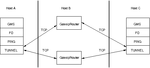
First, the GossipRouter process is created on host B. Note that host B should be outside the firewall,
and all channels in the same group should use the same GossipRouter process. When a channel on host A is
created, its TCPGOSSIP
protocol will register its address with the GossipRouter and retrieve the initial membership (assume this
is C). Now, a TCP connection with the GossipRouter is established by A; this will persist until A crashes
or voluntarily leaves the group. When A multicasts a message to the cluster, GossipRouter looks up all cluster
members (in this case, A and C) and forwards the message to all members, using their TCP connections. In
the example, A would receive its own copy of the multicast message it sent, and another copy would be sent to C.
This scheme allows for example Java applets , which are only allowed to connect back to the host from which they were downloaded, to use JGroups: the HTTP server would be located on host B and the gossip and GossipRouter daemon would also run on that host. An applet downloaded to either A or C would be allowed to make a TCP connection to B. Also, applications behind a firewall would be able to talk to each other, joining a group.
However, there are several drawbacks: first, having to maintain a TCP connection for the duration of the connection might use up resources in the host system (e.g. in the GossipRouter), leading to scalability problems, second, this scheme is inappropriate when only a few channels are located behind firewalls, and the vast majority can indeed use IP multicast to communicate, and finally, it is not always possible to enable outgoing traffic on 2 ports in a firewall, e.g. when a user does not 'own' the firewall.
5.2.6. Health checks
A TUNNEL detects crashes of GosspRouters quickly: when the TCP connection to a GossipRouter is closed, TUNNEL
will add the crashed GossipRouter to a reconnect list, and periodically (reconnect_interval) try to
re-establish a connection.
However, when a GossipRouter hangs, e.g. due to a blocked port in the firewall, or due to a failed switch, then the TCP connection will not be closed and traffic will continue to be sent to that router. This can potentially even block the client on a full TCP send-window.
To be able to close connections to unresponding GossipRouters, a health check has been added to TUNNEL. It can be
activated by setting heartbeat_interval (ms) to a positive value (0 disables health checking). This means that
TUNNEL sends a heartbeat to each GossipRouter it is connected to. When no response has been received for
heartbeat_timeout ms, then the connection to that GossipRouter will be closed.
5.3. The transport in detail
The transport is always the protocol at the bottom of the stack, responsible for sending and receiving messages.
It contains most of the resources, such as the thread pool for handling of incoming messages, sockets for sending and receiving of messages, and thread and socket factories.
The transport is shown in The transport protocol.
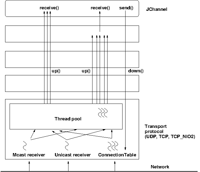
The transport consists of a thread pool (java.util.concurrent.ThreadPoolExecutor) which handles all types of messages
(internal, OOB and regular) and is also used by the timer to fire tasks (e.g. retransmission tasks) at fixed or
dynamic intervals.
When a (UDP or TCP) socket receives a message or message batch, it passes the message to the thread pool for processing.
When the thread pool is disabled, then we use the thread of the caller (e.g. multicast or unicast receiver threads or the ConnectionTable) to send the message up the stack and into the application.
Otherwise, the packet will be processed by a thread from the thread pool, which sends the message up the stack. When all current threads are busy, another thread might be created, up to the maximum number of threads defined. Alternatively, the packet might get dropped if the pool is exhausted.
The point of using a thread pool is that the receiver threads should only receive the packets and forward them to the thread pools for processing, because unmarshalling and processing is slower than simply receiving the message and can benefit from parallelization.
5.3.1. Configuration
Here’s an example of the new configuration:
<UDP
    thread_naming_pattern="cl"
    thread_pool.enabled="true"
    thread_pool.min_threads="0"
    thread_pool.max_threads="100"
    thread_pool.keep_alive_time="20000" />
The attributes for the thread pools are prefixed with thread_pool respectively.
The attributes are listed below. They roughly correspond to the options of java.util.concurrent.ThreadPoolExecutor.
| Name | Description |
|---|---|
thread_naming_pattern |
Determines how threads are named that are running from thread pools in concurrent stack. Valid values include any combination of "cl" letters, where "c" includes the cluster name and "l" includes local address of the channel. The default is "cl". |
enabled |
Whether or not to use a thread pool. If set to false, the caller’s thread is used. |
min_threads |
The minimum number of threads to use. |
max_threads |
The maximum number of threads to use. |
keep_alive_time |
Number of milliseconds until an idle thread is terminated and put back into the pool. |
5.3.2. Message delivery and ordering
A message is considered delivered as soon as the receive() callback returns. While messages are received in a
non-defined order, the reliable protocols (NAKACK2 and UNICAST3) establish an order in which messages are delivered.
Regular messages or message batches from a sender P are delivered in the order in which they were sent. E.g. if P
sent messages 4 and 5, then the application’s receive() callback will be invoked with 4, and when 4 returns, with
message 5. Alternatively, the application might receive a message batch containing messages 4 and 5. When iterating
through that batch, message 4 will be consumed before message 5.
Regular messages from different senders P and Q are delivered in parallel. E.g if P sends 4 and 5 and Q sends 56 and 57,
then the receive() callback might get invoked in parallel for P4 and Q57. Therefore the receive() callback
has to be thread-safe.
In contrast, OOB messages are delivered in an undefined order, e.g. messages P4 and P5 might get delivered as P4 → P5 (P4 followed by P5) in some receivers and P5 → P4 in others. It is also possible that P4 is delivered in parallel with P5, each message getting delivered by a different thread.
The only guarantee for both regular and OOB messages is that a message will get delivered exactly once. Dropped messages are retransmitted and duplicate messages are dropped.
5.3.3. Message processing policy
When a message or message batch is received, it is forwarded to an implementation of MessageProcessingPolicy. The
policy defines how to deliver a message / batch. A number of predefined policies are provided, but custom policies
can be used: to do this, message_processing_policy can be set to the fully qualified name of a class implementing
MessageProcessingPolicy.
The following policies are provided:
| Name | Description |
|---|---|
|
|
|
|
|
|
|
|
Out-of-band messages
OOB messages completely ignore any ordering constraints the stack might have.
This is necessary in cases where we don’t want the message processing to wait until all other messages from the same sender have been processed, e.g. in the heartbeat case: if sender P sends 5 messages and then a response to a heartbeat request received from some other node, then the time taken to process P’s 5 messages might take longer than the heartbeat timeout, so that P might get falsely suspected!
However, if the heartbeat response is marked as OOB, then it will get processed in parallel to the other 5 messages from P and not trigger a false suspicion.
The unit tests UNICAST_OOB_Test and NAKACK_OOB_Test demonstrate how OOB messages influence the ordering,
for both unicast and multicast messages.
5.3.4. Replacing the thread pool and factories
The following thread pools and factories are in TP:
| Name | Description |
|---|---|
Thread pool |
This is the pool for handling incoming messages. It can be fetched using
|
Thread factory |
This is the thread factory ( |
Socket factory |
This is responsible for creation and deletion of sockets. It can be fetched using |
|
|
Note that the thread pool and (thread and socket) factories should be replaced after a channel has been created
and before it is connected (JChannel.connect()).
|
5.3.5. Sharing of thread pools between channels in the same JVM
The thread pool can be shared between instances running inside the same JVM. This can be done by creating an
implementation of Executor, a number of channels and then setting the same executor in all channels via
setThreadPool(Executor e).
The advantage here is that multiple channels running within the same JVM can pool (and therefore save) threads.
The disadvantage is that thread naming will not show to which channel instance an incoming thread belongs to.
5.3.6. Using a custom socket factory
JGroups creates all of its sockets through a SocketFactory, which is located in the transport (TP). The factory has methods to create sockets (Socket, ServerSocket, DatagramSocket and MulticastSocket), close sockets and list all open sockets. Every socket creation method has a service name, which could be for example "jgroups.fd_sock.srv_sock". The service name is used to look up a port (e.g. in a config file) and create the correct socket.
To provide one’s own socket factory, the following has to be done: the code below creates a SocketFactory implementation and sets it in the transport:
JChannel ch;
MySocketFactory factory; // e.g. extends DefaultSocketFactory
ch=new JChannel("config.xml");
ch.setSocketFactory(new MySocketFactory());
ch.connect("demo");
5.4. Handling network partitions
Network partitions can be caused by switch, router or network interface crashes, among other things. If we have a cluster {A,B,C,D,E} spread across 2 subnets {A,B,C} and {D,E} and the switch to which D and E are connected crashes, then we end up with a network partition, with subclusters {A,B,C} and {D,E}.
A, B and C can ping each other, but not D or E, and vice versa. We now have 2 coordinators, A and D. Both subclusters operate independently, for example, if we maintain a shared state, subcluster {A,B,C} replicate changes to A, B and C.
This means, that if during the partition, some clients access {A,B,C}, and others {D,E}, then we end up with different states in both subclusters. When a partition heals, the merge protocol (e.g. MERGE3) will notify A and D that there were 2 subclusters and merge them back into {A,B,C,D,E}, with A being the new coordinator and D ceasing to be coordinator.
The question is what happens with the 2 diverged substates ?
There are 2 solutions to merging substates: first we can attempt to create a new state from the 2 substates, and secondly we can shut down all members of the non primary partition, such that they have to re-join and possibly reacquire the state from a member in the primary partition.
In both cases, the application has to handle a MergeView (subclass of View), as shown in the code below:
public void viewAccepted(View view) {
    if(view instanceof MergeView) {
        MergeView tmp=(MergeView)view;
        List<View> subgroups=tmp.getSubgroups();
        // merge state or determine primary partition
        // run in a separate thread!
    }
}
It is essential that the merge view handling code run on a separate thread if it needs more than a few milliseconds, or else it would block the calling thread.
The MergeView contains a list of views, each view represents a subgroups and has the list of members which formed this group.
5.4.1. Merging substates
The application has to merge the substates from the various subgroups ({A,B,C} and {D,E}) back into one single state for {A,B,C,D,E}. This task has to be done by the application because JGroups knows nothing about the application state, other than it is a byte buffer.
If the in-memory state is backed by a database, then the solution is easy: simply discard the in-memory state and fetch it (eagerly or lazily) from the DB again. This of course assumes that the members of the 2 subgroups were able to write their changes to the DB. However, this is often not the case, as connectivity to the DB might have been severed by the network partition.
Another solution could involve tagging the state with time stamps. On merging, we could compare the time stamps for the substates and let the substate with the more recent time stamps win.
Yet another solution could increase a counter for a state each time the state has been modified. The state with the highest counter wins.
Again, the merging of state can only be done by the application. Whatever algorithm is picked to merge state, it has to be deterministic.
5.4.2. The primary partition approach
The primary partition approach is simple: on merging, one subgroup is designated as the primary partition and all others as non-primary partitions. The members in the primary partition don’t do anything, whereas the members in the non-primary partitions need to drop their state and re-initialize their state from fresh state obtained from a member of the primary partition.
The code to find the primary partition needs to be deterministic, so that all members pick the same primary partition. This could be for example the first view in the MergeView, or we could sort all members of the new MergeView and pick the subgroup which contained the new coordinator (the one from the consolidated MergeView). Another possible solution could be to pick the largest subgroup, and, if there is a tie, sort the tied views lexicographically (all Addresses have a compareTo() method) and pick the subgroup with the lowest ranked member.
Here’s code which picks as primary partition the first view in the MergeView, then re-acquires the state from the new coordinator of the combined view:
public static void main(String[] args) throws Exception {
    final JChannel ch=new JChannel("/home/bela/udp.xml");
    ch.setReceiver(new ReceiverAdapter() {
        public void viewAccepted(View new_view) {
            handleView(ch, new_view);
        }
    });
    ch.connect("x");

    private static void handleView(JChannel ch, View new_view) {
        if(new_view instanceof MergeView) {
            ViewHandler handler=new ViewHandler(ch, (MergeView)new_view);
            // requires separate thread as we don't want to block JGroups
            handler.start();
        }
    }

    private static class ViewHandler extends Thread {
        JChannel ch;
        MergeView view;

        private ViewHandler(JChannel ch, MergeView view) {
            this.ch=ch;
            this.view=view;
        }

        public void run() {
            List<View> subgroups=view.getSubgroups();
            View tmp_view=subgroups.firstElement(); // picks the first
            Address local_addr=ch.getLocalAddress();
            if(!tmp_view.getMembers().contains(local_addr)) {
                System.out.println("Not member of the new primary partition ("
                                   + tmp_view + "), will re-acquire the state");
                try {
                    ch.getState(null, 30000);
                }
                catch(Exception ex) {
                }
            }
            else {
                System.out.println("Not member of the new primary partition ("
                                   + tmp_view + "), will do nothing");
            }
        }
}
The handleView() method is called from viewAccepted(), which is called whenever there is a new view. It spawns a new thread which gets the subgroups from the MergeView, and picks the first subgroup to be the primary partition. Then, if it was a member of the primary partition, it does nothing, and if not, it reaqcuires the state from the coordinator of the primary partition (A).
The downside to the primary partition approach is that work (= state changes) on the non-primary partition is discarded on merging. However, that’s only problematic if the data was purely in-memory data, and not backed by persistent storage. If the latter’s the case, use state merging discussed above.
It would be simpler to shut down the non-primary partition as soon as the network partition is detected, but that a non trivial problem, as we don’t know whether {D,E} simply crashed, or whether they’re still alive, but were partitioned away by the crash of a switch. This is called a split brain syndrome, and means that none of the members has enough information to determine whether it is in the primary or non-primary partition, by simply exchanging messages.
5.4.3. The Split Brain syndrome and primary partitions
In certain situations, we can avoid having multiple subgroups where every subgroup is able to make progress, and on merging having to discard state of the non-primary partitions.
If we have a fixed membership, e.g. the cluster always consists of 5 nodes, then we can run code on a view reception that determines the primary partition. This code
-
assumes that the primary partition has to have at least 3 nodes
-
any cluster which has less than 3 nodes doesn’t accept modfications. This could be done for shared state for example, by simply making the {D,E} partition read-only. Clients can access the {D,E} partition and read state, but not modify it.
-
As an alternative, clusters without at least 3 members could shut down, so in this case D and E would leave the cluster.
The algorithm is shown in pseudo code below:
On initialization:
    - Mark the node as read-only

On view change V:
    - If V has >= N members:
        - If not read-write: get state from coord and switch to read-write
    - Else: switch to read-only
Of course, the above mechanism requires that at least 3 nodes are up at any given time, so upgrades have to be done in a staggered way, taking only one node down at a time. In the worst case, however, this mechanism leaves the cluster read-only and notifies a system admin, who can fix the issue. This is still better than shutting the entire cluster down.
5.5. Large clusters
This section is a collection of best practices and tips and tricks for running large clusters on JGroups. By large clusters, we mean several hundred nodes in a cluster. These recommendations are captured in udp-largecluster.xml which is shipped with JGroups.
|
|
This is work-in-progress, and udp-largecluster.xml is likely to see changes in the future. |
5.6. STOMP support
STOMP is a JGroups protocol which implements the STOMP
protocol. Transactions and acks have not been implemented yet.
Adding the STOMP protocol to a configuration means that
-
Clients written in different languages can subscribe to destinations, send messages to destinations, and receive messages posted to (subscribed) destinations. This is similar to JMS topics.
-
Clients don’t need to join any cluster; this allows for light weight clients, and we can run many of them.
-
Clients can access a cluster from a remote location (e.g. across a WAN).
-
STOMP clients can send messages to cluster members, and vice versa.
The location of a STOMP protocol in a stack is shown in STOMP in a protocol stack.
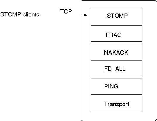
The STOMP protocol should be near the top of the stack.
A STOMP instance listens on a TCP socket for client connections. The port and bind address of the server socket can be defined via properties.
A client can send SUBSCRIBE commands for various destinations. When a SEND for a given destination is received, STOMP adds a header to the message and broadcasts it to all cluster nodes. Every node then in turn forwards the message to all of its connected clients which have subscribed to the same destination. When a destination is not given, STOMP simply forwards the message to all connected clients.
Traffic can be generated by clients and by servers. In the latter case, we could for example have code executing in the address space of a JGroups (server) node. In the former case, clients use the SEND command to send messages to a JGroups server and receive messages via the MESSAGE command. If there is code on the server which generates messages, it is important that both client and server code agree on a marshalling format, e.g. JSON, so that they understand each other’s messages.
Clients can be written in any language, as long as they understand the STOMP protocol. Note that the JGroups STOMP protocol implementation sends additional information (e.g. INFO) to clients; non-JGroups STOMP clients should simply ignore them.
JGroups comes with a STOMP client (org.jgroups.client.StompConnection) and a demo (StompDraw). Both need to be started with the address and port of a JGroups cluster node. Once they have been started, the JGroups STOMP protocol will notify clients of cluster changes, which is needed so client can failover to another JGroups server node when a node is shut down. E.g. when a client connects to C, after connection, it’ll get a list of endpoints (e.g. A,B,C,D). When C is terminated, or crashes, the client automatically reconnects to any of the remaining nodes, e.g. A, B, or D. When this happens, a client is also re-subscribed to the destinations it registered for.
The JGroups STOMP protocol can be used when we have clients, which are either not in the same network segment as the JGroups server nodes, or which don’t want to become full-blown JGroups server nodes. STOMP architecture shows a typical setup.
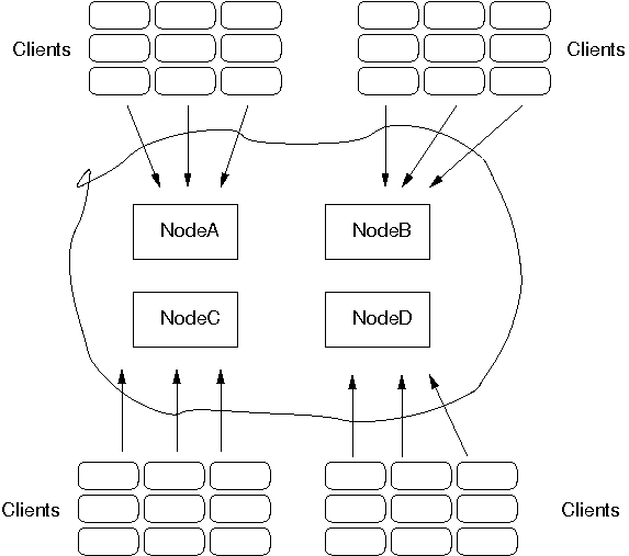
There are 4 nodes in a cluster. Say the cluster is in a LAN, and communication is via IP multicasting (UDP as transport). We now have clients which do not want to be part of the cluster themselves, e.g. because they’re in a different geographic location (and we don’t want to switch the main cluster to TCP), or because clients are frequently started and stopped, and therefore the cost of startup and joining wouldn’t be amortized over the lifetime of a client. Another reason could be that clients are written in a different language, or perhaps, we don’t want a large cluster, which could be the case if we for example have 10 JGroups server nodes and 1000 clients connected to them.
In the example, we see 9 clients connected to every JGroups cluster node. If a client connected to node A sends a message to destination /topics/chat, then the message is multicast from node A to all other nodes (B, C and D). Every node then forwards the message to those clients which have previously subscribed to /topics/chat.
When node A crashes (or leaves) the JGroups STOMP clients (org.jgroups.client.StompConnection) simply pick another server node and connect to it.
For more information about STOMP see the blog entry at http://belaban.blogspot.com/2010/10/stomp-for-jgroups.html.
5.7. Relaying between multiple sites (RELAY2)
|
|
RELAY2 was added to JGroups in the 3.2 release. |
RELAY2 allows for bridging of remote clusters. For example, if we have a cluster in New York (NYC) and another one in San Francisco (SFO), then RELAY2 allows us to bridge NYC and SFO, so that multicast messages sent in NYC will be forwarded to SFO and vice versa.
The NYC and SFO clusters could for example use IP multicasting (UDP as transport), and the bridge could use TCP as transport. The SFO and NYC clusters don’t even need to use the same cluster name.
Relaying between different clusters shows how the two clusters are bridged.
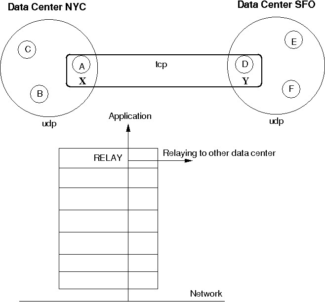
The cluster on the left side with nodes A (the coordinator), B and C is called "NYC" and use IP multicasting (UDP as transport). The cluster on the right side ("SFO") has nodes D (coordinator), E and F.
The bridge between the local clusters NYC and SFO is essentially another cluster with the coordinators (A and D) of the local clusters as members. The bridge typically uses TCP as transport, but any of the supported JGroups transports could be used (including UDP, if supported across a WAN, for instance).
Only a coordinator relays traffic between the local and remote cluster. When A crashes or leaves, then the next-in-line (B) takes over and starts relaying.
Relaying is done via the RELAY2 protocol added to the top of the stack. The bridge is configured with the bridge_props property, e.g. bridge_props="/home/bela/tcp.xml". This creates a JChannel inside RELAY2.
Note that property site must be set in both subclusters. In the example above, we could set site="nyc"
for the NYC subcluster and site="sfo" for the SFO subcluster.
The design is described in detail in JGroups/doc/design/RELAY2.txt (part of the source distribution). In a nutshell, multicast messages received in a local cluster are wrapped and forwarded to the remote cluster by a relay (= the coordinator of a local cluster). When a remote cluster receives such a message, it is unwrapped and put onto the local cluster.
JGroups uses subclasses of UUID to ship the site name with an address. When we see an address with site="nyc" on the SFO side, then RELAY2 will forward the message to the SFO subcluster, and vice versa.
When C multicasts a message in the NYC cluster, A will forward it to D, which will re-broadcast the message on its local cluster, with the sender being D. This means that the sender of the local broadcast will appear as D (so all retransmit requests got to D), but the original sender C is preserved in the header.
At the RELAY2 protocol, the sender will be replaced with the original sender ( nodeC) having site="nyc". When node F wants to reply to the sender of the multicast, the destination of the message will be C, which is intercepted by the RELAY2 protocol and forwarded to the current relay (D). D then picks the correct destination © and sends the message to the remote cluster, where A makes sure C (the original sender) receives it.
An important design goal of RELAY2 is to be able to have completely autonomous clusters, so NYC doesn’t for example have to block waiting for credits from SFO, or a node in the SFO cluster doesn’t have to ask a node in NYC for retransmission of a missing message.
Some notable features of RELAY2 are:
-
Clustering can be done between multiple sites. Currently, sites have to be directly reachable.
-
Virtual (global) views are not provided. If we have clusters SFO={A,B,C} and LON={X,Y,Z}, then both clusters are completed autonomous and don’t know about each other’s existence.
-
Not only unicasts, but also multicasts can be routed between sites (configurable).
To use RELAY2, it has to be placed at the top of the configuration, e.g.:
<relay.RELAY2 site="LON" config="/home/bela/relay2.xml"
              relay_multicasts="true" />
The above configuration has a site name which will be used to route messages between sites. To do that, addresses contain the site-ID, so we always know which site the address is from. E.g. an address A1:LON in the SFO site is not local, but will be routed to the remote site LON.
The relay_multicasts property determines whether or not multicast messages (with dest = null) are relayed to
the other sites, or not. When we have a site LON, connected to sites SFO and NYC, if a multicast message is
sent in site LON, and relay_multicasts is true, then all members of sites SFO and NYC will receive the message.
The config property points to an XML file which defines the setup of the sites, e.g.:
<RelayConfiguration xmlns="urn:jgroups:relay:1.0">

    <sites>
        <site name="lon">
            <bridges>
                <bridge config="/home/bela/global.xml" name="global"/>
            </bridges>
        </site>

        <site name="nyc">
            <bridges>
                <bridge config="/home/bela/global.xml" name="global"/>
            </bridges>
        </site>

        <site name="sfo">
            <bridges>
                <bridge name="global" config="/home/bela/global.xml"/>
            </bridges>
        </site>
    </sites>
</RelayConfiguration>
This defines 3 sites LON, SFO and NYC. All the sites are connected to a global cluster (bus) "global" (defined by /home/bela/global.xml). All inter-site traffic will be sent via this global cluster (which has to be accessible by all of the sites). Intra-site traffic is sent via the cluster that’s defined by the configuration of which RELAY2 is the top protocol.
The above configuration is not mandatory, ie. instead of a global cluster, we could define separate clusters between LON and SFO and LON and NYC. However, in such a setup, due to lack of hierarchical routing, NYC and SFO wouldn’t be able to send each other messages; only LON would be able to send message to SFO and NYC.
5.7.1. Relaying of multicasts
If relay_multicasts is true then any multicast received by the site master of a site (ie. the coordinator of the local cluster, responsible for relaying of unicasts and multicasts) will relay the multicast to all connected sites. This means that - beyond setting relay_multicasts - nothing has to be done in order to relay multicasts across all sites.
A recipient of a multicast message which originated from a different site will see that the sender’s address is not a UUID, but a subclass (SiteUUID) which is the UUID plus the site suffix, e.g. A1:SFO. Since a SiteUUID is a subclass of a UUID, both types can be mixed and matched, placed into hashmaps or lists, and they implement compareTo() and equals() correctly.
When a reply is to be sent to the originator of the multicast message, Message.getSrc() provides the target address for the unicast response message. This is also a SiteUUID, but the sender of the response neither has to know nor take any special action to send the response, as JGroups takes care of routing the response back to the original sender.
5.7.2. Relaying of unicasts
As discussed above, relaying of unicasts is done transparently. However, if we don’t have a target address (e.g. as a result of reception of a multicast), there is a special address SiteMaster which identifies the site master; the coordinator of a local cluster responsible for relaying of messages.
Class SiteMaster is created with the name of a site, e.g. new SiteMaster("LON"). When a unicast with destination SiteMaster("LON") is sent, then we relay the message to the current site master of LON. If the site master changes, messages will get relayed to a different node, which took over the role of the site master from the old (perhaps crashed) site master.
Sometimes only certain members of a site should become site masters; e.g. the more powerful boxes (as routing needs some additional CPU power), or multi-homed hosts which are connected to the external network (over which the sites are connected with each other).
To do this, RELAY2 can generate special addresses which contain the knowledge about whether a member should be skipped when selecting a site master from a view, or not. If can_become_site_master is set to false in RELAY2, then the selection process will skip that member. However, if all members in a given view are marked with can_become_site_master=false, then the first member of the view will get picked.
When we have all members in a view marked with can_become_site_master=false, e.g. {B,C,D}, then B is the site master. If we now start a member A with can_become_site_master=true, then B will stop being the site master and A will become the new site master.
5.7.3. Invoking RPCs across sites
Invoking RPCs across sites is more or less transparent, except for the case when we cannot reach a member of a remote site. If we want to invoke method foo() in A1, A2 (local) and SiteMaster("SFO"), we could write the following code:
List<Address> dests=new ArrayList<Address>(view.getMembers());
dests.add(new SiteMaster("SFO"));
RspList<Object> rsps;
rsps=disp.callRemoteMethods(dests, call,
              new RequestOptions(ResponseMode.GET_ALL, 5000).setAnycasting(true));
for(Rsp rsp: rsps.values()) {
    if(rsp.wasUnreachable())
        System.out.println("<< unreachable: " + rsp.getSender());
    else
        System.out.println("<< " + rsp.getValue() + " from " + rsp.getSender());
}
First, we add the members (A1 and A2) of the current (local) view to the destination set. Then we add the
special address SiteMaster("SFO") which acts as a placeholder for the current coordinator of the SFO site.
Next, we invoke the call with dests as target set and block until responses from all A1, A2 and SiteMaster("SFO") have been received, or until 5 seconds have elapsed.
Next, we check the response list. And here comes the bit that’s new in 3.2: if a site is unreachable, a Rsp has an additional field "unreachable", which means that we could not reach the site master of SFO for example. Note that this is not necessarily an error, as a site maybe currently down, but the caller now has the option of checking on this new status field.
5.7.4. Configuration
Let’s configure an example which consists of 3 sites SFO, LON and NYC and 2 members in each site. First we define the configuration for the local cluster (site) SFO. To do this, we could for example copy udp.xml from the JGroups distro (and name it sfo.xml) and add RELAY2 to the top (as shown above). RELAY2’s config property points to relay2.xml as shown above as well. The relay2.xml file defines a global cluster with global.xml, which uses TCP and MPING for the global cluster (copy for example tcp.xml to create global.xml)
Now copy sfo.xml to lon.xml and nyc.xml. The RELAY2 configuration stays the same for lon.xml and nyc.xml, but the multicast address and/or multicast port has to be changed in order to create 3 separate local clusters. Therefore, modify both lon.xml and nyc.xml and change mcast_port and / or mcast_addr in UDP to use separate values, so the clusters don’t interfere with each other.
To test whether we have 3 different clusters, start the Draw application (shipped with JGroups):
java -Djgroups.bind_addr=127.0.0.1 org.jgroups.demos.Draw -props ./sfo.xml -name sfo1
java -Djgroups.bind_addr=127.0.0.1 org.jgroups.demos.Draw -props ./sfo.xml -name sfo2
java -Djgroups.bind_addr=127.0.0.1 org.jgroups.demos.Draw -props ./lon.xml -name lon1
java -Djgroups.bind_addr=127.0.0.1 org.jgroups.demos.Draw -props ./lon.xml -name lon2
java -Djgroups.bind_addr=127.0.0.1 org.jgroups.demos.Draw -props ./nyc.xml -name nyc1
java -Djgroups.bind_addr=127.0.0.1 org.jgroups.demos.Draw -props ./nyc.xml -name nyc2
We should now have 3 local clusters (= sites) of 2 instances each. When RELAY2.relay_multicasts is true, if you draw in one instance, we should see the drawing in all 6 instances. This means that relaying of multicasting between sites works. If this doesn’t work, run a few Draw instances on global.xml, to see if they find each other.
Note that the first member of each cluster always joins the global cluster (defined by global.xml) too. This is necessary to relay messages between sites.
To test unicasts between sites, you can use the org.jgroups.demos.RelayDemoRpc program: start it as follows:
java org.jgroups.demos.RelayDemoRpc -props ./sfo.xml -name sfo1
Start 2 instances in 3 sites and then use
mcast lon sfo nyc
to invoke RPCs on all local members and site masters SFO, NYC and LON. If one of the sites is down, you’ll get a message stating the site is unreachable.
5.8. Hierarchical/asymmetric routing with RELAY3
RELAY3 is the successor to RELAY2. It has been refactored to concentrate the entire routing logic in a single place,
and it provides asymmetric (hierarchical) routing. Contrary to RELAY2, this means that sites are not necessarily
connected to all other sites.
|
|
RELAY2 and RELAY3 are not compatible, and can therefore not be used in the same network. |
For example, in Asymmetric routing with RELAY3, we have sites HF, NET1, NET2 and NET3:
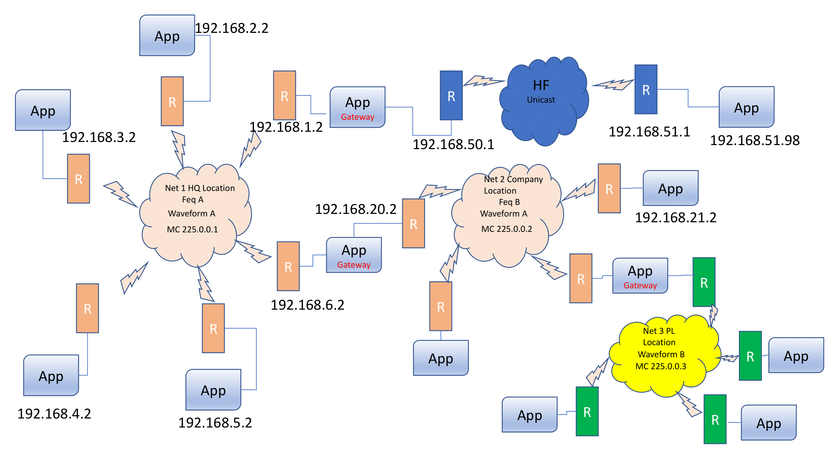
HF is connected to NET1, which in turn is connected to NET2, and NET2 is connected to NET3.
When a member in HF wants to send a message to a member in site NET3, it first needs to send it to the gateway site NET1. The site master in NET1 sees that the target site is not local, and therefore forwards the message according to forwarding rules (discussed below). This means that the message is sent to site NET2, which forwards it to the final destination NET3. There, the site master sees that the target site is local and sends the message to the corresponding member in site NET3.
5.8.1. Forwarding rules
A forwarding rules defines how to process messages whose target site is not local and not a directly connected site. E.g.:
<bridges>
    <bridge name="bridge-net1-net2" config="/Users/bela/bridge-net1-net2.xml"/>
    <bridge name="bridge-net1-hf"   config="/Users/bela/bridge-net1-hf.xml"/>
</bridges>
<forwards>
    <forward to="net3" gateway="net2"/>
</forwards>
The snippet above is from NET1. It defines 2 bridges, namely one to site NET2 and one to HF. This means that site NET1 is directly connected to sites HF and NET2 (see Asymmetric routing with RELAY3 above).
The new part is the <forwards/> section, which defines a rule how to send messages from the local site (NET1) to
site NET3. Because messages from NET1 can reach NET3 only through gateway site NET2, the forwarding rule as shown
in (1) is added. This means that all messages to site "net3" have to be forwarded to (gateway) site "net2".
It is also possible to use wildcards in forwarding rules:
<forwards>
    <forward to=".*" gateway="net2"/>
</forwards>
This is from NET3 and defines that all messages that are not local should be forwarded via gateway site NET2.
5.8.2. Sending a message to all site masters
The SiteMaster(String site) can be used to send a message to the site master of site. RELAY3 now allows for site to be null: this means that a message is sent to all site masters.
5.8.3. Getting information about the topology
RELAY3 added functionality to fetch the topology, ie. information about all sites and their members across an entire network. In addition, callbacks can be registered when a member join or leaves anywhere in the network, ie. in any site, or when a site goes down or comes up.
To fetch the current topology, the following code can be used:
JChannel ch;
RELAY r=ch.getProtocolStack().findProtocol(RELAY.class);
Topology topo=r.topo();
Map<String,View> m=topo.cache(); // all sites and their views
// alternatively:
System.out.printf("sites:\n%s\n", topo.print());
To get notified when a member joins or leaves, a view handler can be registered with Topology:
topo.setViewHandler((s,v) -> System.out.printf("site %s: new view: %s\n", s, v));To register when a site goes down or comes up, RELAY.setRouteStatusListener(RouteStatusListener l) can be used.
There’s an additional callback in RELAY3 to register when a member becomes site master, or ceases to be
site master: setSiteMasterListener(Consumer<Boolean> l). The argument is true when the member just became
site master, and false otherwise.
5.8.4. Samples
The definition of the network described above (Asymmetric routing with RELAY3) is defined in 4 configuration files in
https://github.com/belaban/JGroups/tree/master/conf/relay/: hf.xml, net1.xml, net2.xml and net3.xml.
The 3 bridges are defined in the 3 bridge-*.xml files.
To use the config files to run a demo (e.g. RelayDemo), the IP addresses of the files have to be changed.
A sample config (e.g. net1.xml) looks as follows (edited for brevity):
<config xmlns:xsi="http://www.w3.org/2001/XMLSchema-instance"
        xmlns="urn:org:jgroups"
        xsi:schemaLocation="urn:org:jgroups http://www.jgroups.org/schema/jgroups.xsd">
    <UDP
         bind_addr="192.168.2.2"
         bind_port="7000"
         mcast_addr="225.0.0.1" />

    <PING />
    <pbcast.NAKACK2 xmit_interval="500"
                    discard_delivered_msgs="true" />
    <relay.RELAY3 site="net1"
                 max_site_masters="1"
                 can_become_site_master="true">
        <RelayConfiguration xmlns="urn:jgroups:relay:1.0"
                    xmlns:xsi="http://www.w3.org/2001/XMLSchema-instance"
                    xsi:schemaLocation="urn:jgroups:relay:1.0 relay.xsd">
            <sites>
                <site name="net1">
                    <bridges>
                        <bridge name="bridge-net1-net2" config="/Users/bela/bridge-net1-net2.xml"/>
                        <bridge name="bridge-net1-hf"   config="/Users/bela/bridge-net1-hf.xml"/>
                    </bridges>
                    <forwards>
                        <forward to="net3" gateway="net2"/>
                    </forwards>
                </site>
            </sites>
        </RelayConfiguration>
    </relay.RELAY3>
    <UNICAST3 xmit_interval="500" />
    <pbcast.STABLE desired_avg_gossip="50000"
                   max_bytes="8m"/>
    <pbcast.GMS print_local_addr="true" join_timeout="1000" />
</config>|
|
The above configuration requires modifications; bind_addr, mcast_addr and the location of the bridge files
(e.g. /Users/bela/bridge-net1-net2.xml) need to be changed.
|
5.8.5. Reliability of messages across sites
A downside of RELAY2 has always been that messages between sites can be dropped, e.g. in the following scenario:
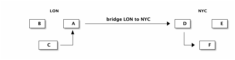
-
Sites LON with members {A,B,C} and NYC with {D,E,F}; A and D are site masters
-
C:lon sends a message M to F:nyc
-
This means C:lon sends M to A:lon, which forwards it to D:nyc, which then forwards it to F:nyc
-
-
Before F:nyc receives M, the following can happen:
-
Site master A crashes. Although B will become site master a few milliseconds later → M is lost
-
Site master D:nyc crashes. Before E:nyc can take over → M is lost
-
Applications would typically either use blocking RPCs or some ack to know that a message was received by the target in a different site.
The reason for the potential loss of M is that M is not retransmitted across sites, unlike in the local cluster.
Enter RELAY3: the configuration in [ReliableRELAY3] above has UNICAST3 above RELAY3, so unicasts will be
retransmitted, regardless of whether the destination is in the local cluster or in a remote site. This looks as follows:
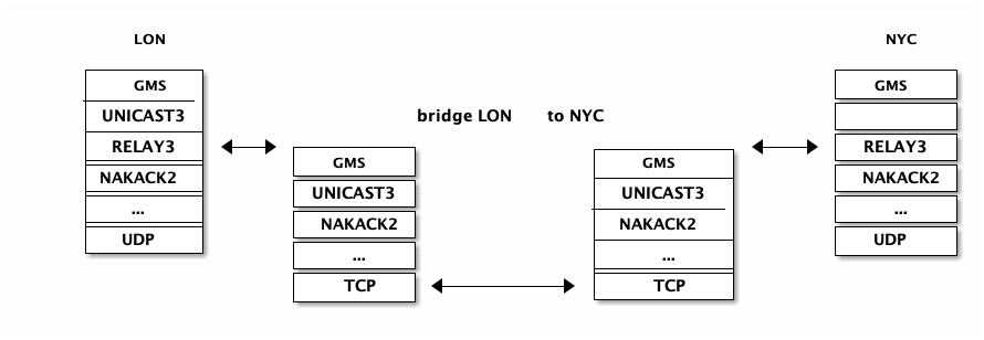
|
|
Reliability currently applies only to unicast messages, not to multicast messages! Reliable multicast messages will be investigated in https://issues.redhat.com/browse/JGRP-2738. |
Of course, RELAY3 can still be on top of the stack, above UNICAST3, but then unicast messages wold not get
retransmitted, resulting in the same behavior as with RELAY2.
However, the above configuration is recommended for RELAY3. If a specific messages doesn’t need to be retransmitted
across sites, flag NO_RELIABILITY can be set. This allows a user to define on a per-message basis whether or not to
enable or disable retransmission across sites.
In the example above, the following would happen:
-
Site master A crashes:
-
M is retransmitted
-
B becomes site master → retransmission ensures that B will eventually receive M
-
-
Site master D:nyc crashes
-
M is retransmitted
-
New site master E:nyc receives and forwards M to F:nyc
-
Stopping of retransmission to dead members / sites
In the above example, retransmission of M ensures that M will eventually be received. However, what happens when F:nyc crashes, or the entire site "nyc" crashes?
When F:nyc crashes, the site master of "nyc" (either D or E) sends a MBR-UNREACHABLE message back to the sender of M (C:lon). This triggers 2 actions:
-
C’s
RouteStatusListener.memberUnreachable(Address m)method (inRELAY3) will be invoked -
In
UNICAST3of C, the sender entry for F:nyc will be removed, stopping retransmission of M
When members D, E and F of site "nyc" crash, then a SITE-UNREACHABLE message will be sent to C:lon. This causes 2 actions:
-
C’s
RouteStatusListener.siteUnreachable()method (inRELAY3) will be invoked -
In
UNICAST3of C, the sender entry for F:nyc will be removed, stopping retransmission of M
5.8.6. Multiple site masters with RELAY3
When we have multiple site masters (e.g. RELAY3.max_site_masters="2"), then messages between sites can be routed
through a different site master every time when the SiteMasterPicker uses a load balancing strategy.
This is fine when the target is a unicast destination, e.g. F:nyc in the example above.
However, when the destination is a site master (e.g. SiteMaster("nyc"), then the following issue exists:
-
C:lon sends 5 unicast messages to
SiteMaster("nyc")" -
For messages 1-3, site master A:lon picks D:nyc
-
For messages 4-5, A:lon picks E:nyc
-
C:lon get acks for messages 1-2 from D:nyc, and removes these messages from its send table
-
E:nyc sees message 4-5 from C:lon, and asks C:lon for the first message
-
C:lon sends message 3 as its first message to E:nyc
So D:nyc received messages 1-3, and E:nyc received messages 3-5 → message 3 was received by both site masters. Even worse, depending on when A:lon gets the ack from D:nyc (for example, later), it might resend messages 1-3 to E:nyc.
To avoid these duplicate messages, the site master picker in RELAY3 is by default set to StickySiteMasterPicker. This
implementation caches the site master it picked for a given sender, and picks a random site master if not yet cached.
In the above example, site master A:lon would therefore either pick D:nyc or E:nyc, but stick with the selected
site master once it has picked one. It would therefore send all 5 messages to either D:nyc or E:nyc, and continue to
do so until the selected site master crashed, and then select a new one.
5.9. Daisychaining
Daisychaining refers to a way of disseminating messages sent to the entire cluster.
The idea behind it is that it is inefficient to broadcast a message in clusters where IP multicasting is not available. For example, if we only have TCP available (as is the case in most clouds today), then we have to send a broadcast (or group) message N-1 times. If we want to broadcast M to a cluster of 10, we send the same message 9 times.
Example: if we have {A,B,C,D,E,F}, and A broadcasts M, then it sends it to B, then to C, then to D etc. If we have a 1 GB switch, and M is 1GB, then sending a broadcast to 9 members takes 9 seconds, even if we parallelize the sending of M. This is due to the fact that the link to the switch only sustains 1GB / sec. (Note that I’m conveniently ignoring the fact that the switch will start dropping packets if it is overloaded, causing TCP to retransmit, slowing things down)…
Let’s introduce the concept of a round. A round is the time it takes to send or receive a message.
In the above example, a round takes 1 second if we send 1 GB messages.
In the existing N-1 approach, it takes X * (N-1) rounds to send X messages to a cluster of N nodes.
So to broadcast 10 messages a the cluster of 10, it takes 90 rounds.
The idea is that, instead of sending a message to N-1 members, we only send it to our neighbor, which forwards it to its neighbor, and so on. For example, in {A,B,C,D,E}, D would broadcast a message by forwarding it to E, E forwards it to A, A to B, B to C and C to D. We use a time-to-live field, which gets decremented on every forward, and a message gets discarded when the time-to-live is 0.
The advantage is that, instead of taxing the link between a member and the switch to send N-1 messages, we distribute the traffic more evenly across the links between the nodes and the switch. Let’s take a look at an example, where A broadcasts messages m1 and m2 in cluster {A,B,C,D}, '-->' means sending:
5.9.1. Traditional N-1 approach
-
Round 1: A(m1) --> B
-
Round 2: A(m1) --> C
-
Round 3: A(m1) --> D
-
Round 4: A(m2) --> B
-
Round 5: A(m2) --> C
-
Round 6: A(m2) --> D
It takes 6 rounds to broadcast m1 and m2 to the cluster.
5.9.2. Daisychaining approach
-
Round 1: A(m1) --> B
-
Round 2: A(m2) --> B || B(m1) --> C
-
Round 3: B(m2) --> C || C(m1) --> D
-
Round 4: C(m2) --> D
In round 1, A send m1 to B.
In round 2, A sends m2 to B, but B also forwards m1 (received in round 1) to C.
In round 3, A is done. B forwards m2 to C and C forwards m1 to D (in parallel, denoted by ||).
In round 4, C forwards m2 to D.
5.9.3. Switch usage
Let’s take a look at this in terms of switch usage: in the N-1 approach, A can only send 125MB/sec, no matter how many members there are in the cluster, so it is constrained by the link capacity to the switch. (Note that A can also receive 125MB/sec in parallel with today’s full duplex links).
So the link between A and the switch gets hot.
In the daisychaining approach, link usage is more even: if we look for example at round 2, A sending to B and B sending to C uses 2 different links, so there are no constraints regarding capacity of a link. The same goes for B sending to C and C sending to D.
In terms of rounds, the daisy chaining approach uses X + (N-2) rounds, so for a cluster size of 10 and broadcasting 10 messages, it requires only 18 rounds, compared to 90 for the N-1 approach!
5.9.4. Performance
To measure performance of DAISYCHAIN, a performance test (test.Perf) was run, with 4 nodes connected to a 1 GB switch; and every node sending 1 million 8K messages, for a total of 32GB received by every node. The config used was tcp.xml.
The N-1 approach yielded a throughput of 73 MB/node/sec, and the daisy chaining approach 107MB/node/sec!
5.9.5. Configuration
DAISYCHAIN can be placed directly on top of the transport, regardless of whether it is UDP or TCP, e.g.
<TCP .../>
<DAISYCHAIN .../>
<TCPPING .../>|
|
Daisychaining is experimental. While results show that performance for multicast messages (= messages to all cluster nodes) is excellent, it has never been tested extensively. |
5.10. Tagging messages with flags
A message can be tagged with a selection of flags, which alter the way certain protocols treat the message. This is done as follows:
Message msg=new BytesMessage().setFlag(Message.Flag.OOB, Message.Flag.NO_FC);Here we tag the message to be OOB (out of band) and to bypass flow control.
The advantage of tagging messages is that we don’t need to change the configuration, but instead can override it on a per-message basis.
The available flags are:
- Message.OOB
-
This tags a message as out-of-band, which will get it processed by the out-of-band thread pool at the receiver’s side. Note that an OOB message does not provide any ordering guarantees, although OOB messages are reliable (no loss) and are delivered only once. See Out-of-band messages for details.
- Message.DONT_BUNDLE
-
This flag causes the transport not to bundle the message, but to send it immediately. See Message bundling and performance for a discussion of the DONT_BUNDLE flag with respect to performance of blocking RPCs.
- Message.NO_FC
-
This flag bypasses any flow control protocol (see Flow control) for a discussion of flow control protocols.
- Message.NO_RELIABILITY
-
When sending unicast or multicast messages, some protocols (
UNICAST3,NAKACK2) add sequence numbers to the messages in order to (1) deliver them reliably and (2) in order.
If we don’t want reliability, we can tag the message with flagNO_RELIABILITY. This means that a message tagged with this flag may not be received, may be received more than once, or may be received out of order.
A message tagged withNO_RELIABILITYwill simply bypass reliable protocols such asUNICAST3andNAKACK2.
For example, if we send multicast message M1, M2 (NO_RELIABILITY), M3 and M4, and the starting sequence number is #25, then M1 will have seqno #25, M3 will have #26 and M4 will have #27. We can see that we don’t allocate a seqno for M2 here. - Message.NO_TOTAL_ORDER
-
If we use a total order configuration with SEQUENCER (SEQUENCER), then we can bypass SEQUENCER (if we don’t need total order for a given message) by tagging the message with flag
NO_TOTAL_ORDER. - Message.NO_RELAY
-
If we use RELAY (see [RelayAdvanced]) and don’t want a message to be relayed to the other site(s), then we can tag the message with NO_RELAY.
- Message.RSVP
-
When this flag is set, a message send will block until the receiver (unicast) or receivers (multicast) have acked reception of the message, or until a timeout occurs. See Synchronous messages for details.
- Message.RSVP_NB
-
This is the same as RSVP, but doesn’t block the sender of a message (invoker of an RPC). The call therefore returns immediately, but RSVP will resend the message until it has received all acks, or the timeout kicked in.
- Message.DONT_LOOPBACK
-
If this flag is set and the message is a multicast message (dest == null), then the transport by default (1) multicasts the message, (2) loops it back up the stack (on a separate thread) and (3) discards the multicast when received.
When DONT_LOOPBACK is set, the message will be multicast, but it will not be looped back up the stack. This is useful for example when the sender doesn’t want to receive its own multicast. Contrary to JChannel.setDiscardOwnMessages(), this flag can be set per message and the processing is done at the transport level rather than the JChannel level.
An example is the Discovery protocol: when sending a discovery request, the sender is only interested in responses from other members and therefore doesn’t need to receive its own discovery multicast request.
Note that this is a transient flag, so Message.setTransientFlag() has to be used instead of Message.setFlag()
|
|
Note that DONT_LOOPBACK does not make any sense for unicast messages,
as the sender of a message sent to itself will never receive it.
|
- Message.DONT_BLOCK
-
If set, the message will be dropped if the TransferQueueBundler’s queue is full, rather than the sender thread blocking. This means, the message will not block on the send in the transport.
5.11. Performance tests
There are a number of performance tests shipped with JGroups. The section below discusses MPerf and UPerf.
5.11.1. MPerf
MPerf is a test which measures multicast performance. This doesn’t mean IP multicast performance, but point-to-multipoint performance. Point-to-multipoint means that we measure performance of one-to-many messages; in other words, messages sent to all cluster members.
MPerf is dynamic; it doesn’t need a setup file to define the number of senders, number of messages to be sent and message size.
Instead, all the configuration needed by an instance of MPerf is an XML stack configuration, and configuration changes done in one member are automatically broadcast to all other members.
MPerf can be started as follows:
java -cp $CLASSPATH org.jgroups.tests.perf.MPerf -props ./fast.xml
This assumes that we’re using IPv4 addresses (otherwise IPv6 addresses are used) and the JGroups JAR on the classpath.
A screen shot of MPerf looks like this (could be different, depending on the JGroups version):
[belasmac] /Users/bela$ mperf.sh -props ~/fast.xml -name A


----------------------- MPerf -----------------------
Date: Mon Sep 05 14:26:55 CEST 2016
Run by: bela
JGroups version: 4.0.0-SNAPSHOT


-------------------------------------------------------------------
GMS: address=A, cluster=mperf, physical address=127.0.0.1:52344
-------------------------------------------------------------------
** [A|0] (1) [A]
[1] Send [2] View
[3] Set num msgs (1000000) [4] Set msg size (1KB) [5] Set threads (10) [6] New config (/Users/bela/fast.xml)
[7] Number of senders (all) [o] Toggle OOB (false)
[x] Exit this [X] Exit all [c] Cancel sending
We’re starting MPerf with -props ~/fast.xml and -name A. The -props option
points to a JGroups configuration file, and -name gives the member the name "A".
A few instances of MPerf can now be started and each instance should join the same cluster.
MPerf can then be run by pressing [1]. In this case, every member in the cluster (in the example, we have members A and B) will send 1 million 1K messages. Once all messages have been received, MPerf will write a summary of the performance results to stdout:
1
[1] Send [2] View
[3] Set num msgs (1000000) [4] Set msg size (1KB) [5] Set threads (10) [6] New config (/Users/bela/fast.xml)
[7] Number of senders (all) [o] Toggle OOB (false)
[x] Exit this [X] Exit all [c] Cancel sending
-- sending 1000000 msgs
++ sent 100000
-- received 200000 msgs (217 ms, 921658.99 msgs/sec, 921.66MB/sec)
++ sent 200000
++ sent 300000
-- received 400000 msgs (225 ms, 888888.89 msgs/sec, 888.89MB/sec)
++ sent 400000
++ sent 500000
-- received 600000 msgs (228 ms, 877192.98 msgs/sec, 877.19MB/sec)
++ sent 600000
++ sent 700000
-- received 800000 msgs (277 ms, 722021.66 msgs/sec, 722.02MB/sec)
++ sent 800000
++ sent 900000
-- received 1000000 msgs (412 ms, 485436.89 msgs/sec, 485.44MB/sec)
++ sent 1000000
-- received 1200000 msgs (305 ms, 655737.7 msgs/sec, 655.74MB/sec)
-- received 1400000 msgs (294 ms, 680272.11 msgs/sec, 680.27MB/sec)
-- received 1600000 msgs (228 ms, 877192.98 msgs/sec, 877.19MB/sec)
-- received 1800000 msgs (223 ms, 896860.99 msgs/sec, 896.86MB/sec)
-- received 2000000 msgs (237 ms, 843881.86 msgs/sec, 843.88MB/sec)

Results:

A: 2000000 msgs, 2GB received, time=2646ms, msgs/sec=755857.9, throughput=755.86MB
B: 2000000 msgs, 2GB received, time=2642ms, msgs/sec=757002.27, throughput=757MB

===============================================================================
 Average/node:    2000000 msgs, 2GB received, time=2644ms, msgs/sec=756429.65, throughput=756.43MB
 Average/cluster: 4000000 msgs, 4GB received, time=2644ms, msgs/sec=1512859.3, throughput=1.51GB
================================================================================
In the sample run above, we see member A’s screen. A sends 1 million messages and waits for its 1 million and the 1 million messages from B to be received before it dumps some stats to stdout. The stats include the number of messages and bytes received, the time, the message rate and throughput averaged over the 2 members. It also shows the aggregated performance over the entire cluster.
In the sample run above (both processes on the same box), we got an average 756 MB of data per member per second, and an aggregated 1.5 GB per second for the entire cluster (A and B in this case).
Parameters such as the number of messages to be sent, the message size and the number of threads to be used to send the messages can be configured by pressing the corresponding numbers. After pressing return, the change will be broadcast to all cluster members, so that we don’t have to go to each member and apply the same change. Also, new members started, will fetch the current configuration and apply it.
For example, if we set the message size in A to 2000 bytes, then the change would be sent to B, which would apply it as well. If we started a third member C, it would also have a configuration with a message size of 2000.
Another feature is the ability to restart all cluster members with a new configuration. For example, if we modified ./fast.xml, we could select [6] to make all cluster members disconnect and close their existing channels and start a new channel based on the modified fast.xml configuration.
The new configuration file doesn’t even have to be accessible on all cluster members; only on the member which makes the change. The file contents will be read by that member, converted into a byte buffer and shipped to all cluster members, where the new channel will then be created with the byte buffer (converted into an input stream) as config.
Being able to dynamically change the test parameters and the JGroups configuration makes MPerf suited to be run in larger clusters; unless a new JGroups version is installed, MPerf will never have to be restarted manually.
5.11.2. UPerf
UPerf is used to measure point-to-point (= unicast) communication between members. Start a few members like this:
java -cp $CLASSPATH org.jgroups.tests.perf.UPerf -props ./fast.xml
They will form a cluster. When [1] is pressed, every node will invoke 20000 synchronous RPCs on other members, each
time randomly selecting a member from the cluster. This will be done by 25 threads, but both number of RPCs and sender
threads can be changed dynamically across the entire cluster at runtime.
With an 80% chance, a request will mimic a GET which is a small request returning a (by default) 1K response. With a 20%
chance, the request is a PUT which is a 1K request and a small response. The read-write ration can be changed via [r].
GETs and PUTs mimic a distributed cache where GETs query information from the cache and PUT update information.
When done, every member sends its results back to the node on which the test was started, which then tallies the results, computes averages etc and prints the result of this round to stdout.
Here’s a sample run on member A:
[1] Invoke RPCs [6] Sender threads (25) [7] Num msgs (20000) [8] Msg size (1KB)
[s] Sync (true) [o] OOB (true) [b] Msg bundling (true)
[a] Anycast count (2) [r] Read percentage (0.80)
[l] local gets (false) [d] print details (false)  [i] print invokers (false)
[v] View [x] Exit [X] Exit all

1
invoking 20000 RPCs of 1KB, sync=true, oob=true, msg_bundling=true
.........

done (in 877 ms)

======================= Results: ===========================
D: 23121.39 reqs/sec (15813 gets, 4187 puts, get RTT 971.37 us, put RTT 1495.74 us)
A: 22805.02 reqs/sec (15826 gets, 4174 puts, get RTT 992.44 us, put RTT 1541.44 us)
B: 24449.88 reqs/sec (15807 gets, 4193 puts, get RTT 873.63 us, put RTT 1551.84 us)
C: 22371.36 reqs/sec (15826 gets, 4174 puts, get RTT 937.02 us, put RTT 1755.55 us)


Throughput: 23161.55 reqs/sec/node (23.16MB/sec)
Roundtrip:  gets avg = 932.40 us, puts avg = 1646.17 us
This run was on a cluster consisting of {A,B,C,D} and the test was initiated on member A. When everyone is done, the results for A, B, C and D are printed individually, then averages for throughout and round-trip times are computed and also printed to stdout.
In this round, every node managed to invoke roughly 23'000 sync RPCs per second on randomly selected other members. The average GET time was slightly under 1 ms and PUT was roughly 1.6 ms.
5.12. Ergonomics
Ergonomics is similar to the dynamic setting of optimal values for the JVM, e.g. garbage collection, memory sizes etc. In JGroups, ergonomics means that we try to dynamically determine and set optimal values for protocol properties. Examples are thread pool size, flow control credits, heartbeat frequency and so on.
There is an ergonomics property which can be enabled or disabled for every protocol. The default is true. To disable it, set it to false, e.g.:
<UDP... />
<PING ergonomics="false"/>
Here we leave ergonomics enabled for UDP (the default is true), but disable it for PING.
Ergonomics is work-in-progress, and will be implemented over multiple releases.
5.13. Probe
Probe is the Swiss Army Knife of JGroups; it allows to fetch information about the members running in a cluster, get and set properties of the various protocols, and invoke methods in all cluster members.
Probe can even insert protocols into running cluster members, or remove/replace existing protocols. Note that this doesn’t make sense though with stateful protocols such as NAKACK. But this feature is helpful, it could be used for example to insert a diagnostics or stats protocol into a running system. When done, the protocol can be removed again.
Probe is a script (probe.sh in the bin directory of the source
distribution) that can be invoked on any of the hosts in same network in which a cluster is running. The probe.sh script
essentially calls org.jgroups.tests.Probe which is part of the JGroups JAR.
Otherwise, probe can be run as follows:
java -cp jgroups.jar org.jgroups.tests.Probe
|
|
Probe by default uses IP multicasting to send probe requests to all cluster nodes. However, if IP multicasting
is not available or disabled in a network, probe can also be given the address of a single member
via the -addr option. That member then returns the addresses of the other cluster members, and probe
sends the request to all members individually.
|
The way probe works is that every stack has an additional multicast socket that by default listens on 224.0.75.75:7500 for diagnostics requests from probe. The configuration is located in the transport protocol (e.g. UDP), and consists of the following properties:
| Name | Description |
|---|---|
diag.enabled |
Whether or not to enable diagnostics (default: true). When enabled, this will create a MulticastSocket and we have one additional thread listening for probe requests. When disabled, we’ll have neither the thread nor the socket created. |
diag.enable_udp |
Use a multicast socket to listen for probe requests |
diag.enable_tcp |
Use a TCP socket to listen for probe requests (ignored if |
diag.mcast_addr |
The multicast address which the MulticastSocket should join. The default is
|
diag.bind_addr |
Bind address for diagnostic probing. Used when diag_enable_tcp is true") |
diag.port |
The port on which the MulticastSocket should listen. The default is |
Probe is extensible; by implementing a ProbeHandler and registering it with the transport (TP.registerProbeHandler()), any protocol, or even applications can register functionality to be invoked via probe. Refer to the javadoc for details.
To get information about the cluster members running in the local network, we can use the following probe command:
[belasmac] /Users/bela$ probe.sh

-- sending probe on /224.0.75.75:7500


#1 (100 bytes):
local_addr=B
physical_addr=127.0.0.1:52060
view=[A|1] (2) [A, B]
cluster=draw
version=4.0.0-SNAPSHOT

#2 (100 bytes):
local_addr=A
physical_addr=127.0.0.1:60570
view=[A|1] (2) [A, B]
cluster=draw
version=4.0.0-SNAPSHOT


2 responses (2 matches, 0 non matches)
[belasmac] /Users/bela$
This gets us 2 responses, from A and B. "A" and "B" are the logical names, but we also see the UUIDs.
They’re both in the same cluster ("draw") and both have the same view
([A|1] [A, B]). The physical address and the version of both members is also shown.
Note that probe.sh -help lists the command line options.
To fetch all of the JMX information from all protocols, we can invoke probe jmx.
However, this dumps all of the JMX attributes from all protocols of all cluster members, so make sure to pipe the output into a file and awk and sed it for legibility!
However, we can also JMX information from a specific protocol, e.g. FRAG2 (slightly edited>:
[linux]/home/bela$ probe.sh FRAG2

-- send probe on /224.0.75.75:7500


#1 (318 bytes):
local_addr=B [88588976-5416-b054-ede9-0bf8d4b56c02]
cluster=DrawGroupDemo
physical_addr=192.168.1.5:35841
jmx=FRAG2={id=5, level=off, num_received_msgs=131, frag_size=60000,
           num_sent_msgs=54, stats=true, num_sent_frags=0,
           name=FRAG2, ergonomics=true, num_received_frags=0}

view=[A|1] [A, B]
version=3.0.0.Beta1


#2 (318 bytes):
local_addr=A [1a1f543c-2332-843b-b523-8d7653874de7]
cluster=DrawGroupDemo
physical_addr=192.168.1.5:43283
jmx=FRAG2={id=5, level=off, num_received_msgs=131, frag_size=60000,
           num_sent_msgs=77, stats=true, num_sent_frags=0,
           name=FRAG2, ergonomics=true, num_received_frags=0}

view=[A|1] [A, B]
version=3.0.0.Beta1


2 responses (2 matches, 0 non matches)
[linux]/home/bela$
We can also get information about specific properties in a given protocol:
[belasmac] /Users/bela$ probe.sh NAKACK2.xmit

-- sending probe on /224.0.75.75:7500


#1 (597 bytes):
local_addr=A [ip=127.0.0.1:63259, version=4.0.0-SNAPSHOT, cluster=draw, 2 mbr(s)]
NAKACK2={xmit_from_random_member=false, xmit_interval=500, xmit_reqs_received=0, xmit_reqs_sent=0, xmit_rsps_received=0, xmit_rsps_sent=0, xmit_table_capacity=204800, xmit_table_max_compaction_time=30000, xmit_table_missing_messages=0, xmit_table_msgs_per_row=2000, xmit_table_num_compactions=0, xmit_table_num_current_rows=100, xmit_table_num_moves=0, xmit_table_num_purges=1, xmit_table_num_resizes=0, xmit_table_num_rows=100, xmit_table_resize_factor=1.2, xmit_table_undelivered_msgs=0, xmit_task_running=true}


#2 (597 bytes):
local_addr=B [ip=127.0.0.1:62737, version=4.0.0-SNAPSHOT, cluster=draw, 2 mbr(s)]
NAKACK2={xmit_from_random_member=false, xmit_interval=500, xmit_reqs_received=0, xmit_reqs_sent=0, xmit_rsps_received=0, xmit_rsps_sent=0, xmit_table_capacity=204800, xmit_table_max_compaction_time=30000, xmit_table_missing_messages=0, xmit_table_msgs_per_row=2000, xmit_table_num_compactions=0, xmit_table_num_current_rows=100, xmit_table_num_moves=0, xmit_table_num_purges=1, xmit_table_num_resizes=0, xmit_table_num_rows=100, xmit_table_resize_factor=1.2, xmit_table_undelivered_msgs=0, xmit_task_running=true}


2 responses (2 matches, 0 non matches)
[belasmac] /Users/bela$
This returns all JMX attributes that start with "xmit" in all NAKACK2 protocols of
all cluster members. We can also pass a list of attributes:
[belasmac] /Users/bela$ probe.sh NAKACK2.xmit,num

-- sending probe on /224.0.75.75:7500


#1 (646 bytes):
local_addr=A [ip=127.0.0.1:63259, version=4.0.0-SNAPSHOT, cluster=draw, 2 mbr(s)]
NAKACK2={num_messages_received=115, num_messages_sent=26, xmit_from_random_member=false, xmit_interval=500, xmit_reqs_received=0, xmit_reqs_sent=0, xmit_rsps_received=0, xmit_rsps_sent=0, xmit_table_capacity=204800, xmit_table_max_compaction_time=30000, xmit_table_missing_messages=0, xmit_table_msgs_per_row=2000, xmit_table_num_compactions=0, xmit_table_num_current_rows=100, xmit_table_num_moves=0, xmit_table_num_purges=1, xmit_table_num_resizes=0, xmit_table_num_rows=100, xmit_table_resize_factor=1.2, xmit_table_undelivered_msgs=0, xmit_task_running=true}


#2 (646 bytes):
local_addr=B [ip=127.0.0.1:62737, version=4.0.0-SNAPSHOT, cluster=draw, 2 mbr(s)]
NAKACK2={num_messages_received=115, num_messages_sent=89, xmit_from_random_member=false, xmit_interval=500, xmit_reqs_received=0, xmit_reqs_sent=0, xmit_rsps_received=0, xmit_rsps_sent=0, xmit_table_capacity=204800, xmit_table_max_compaction_time=30000, xmit_table_missing_messages=0, xmit_table_msgs_per_row=2000, xmit_table_num_compactions=0, xmit_table_num_current_rows=100, xmit_table_num_moves=0, xmit_table_num_purges=1, xmit_table_num_resizes=0, xmit_table_num_rows=100, xmit_table_resize_factor=1.2, xmit_table_undelivered_msgs=0, xmit_task_running=true}


2 responses (2 matches, 0 non matches)
[belasmac] /Users/bela$
This returns all attributes of NAKACK2 that start with "xmit" or "num".
To invoke an operation, e.g. to set the logging level in all UDP protocols from "warn" to "trace", we
can use probe.sh UPD.setLevel["trace"]. This raises the logging level in all
UDP protocols of all cluster members, which is useful to diagnose a running system.
Operation invocation uses reflection, so any method defined in any protocol can be invoked. This is a powerful tool to get diagnostics information from a running cluster.
For further information, refer to the command line options of probe (probe.sh -h).
5.13.1. Looking at details of RPCs with probe
Probe can also be used to inspect for every node P:
-
the number of unicast RPCs invoked (sync or async)
-
the number of multicast RPCs invoked (sync or async)
-
the number of anycast RPCs invoked (sync or async)
For sync RPCs, it is also possible to get the min/max/avg times for RPCs to a given destination.
Since taking the times for all sync RPCs takes time (2x System.nanoTime() for each RPC), this is disabled by default
and has to be enabled (assuming we have 4 nodes running):
probe.sh rpcs-enable-details
From now on, timings for sync RPCs will be taken (async RPCs are not timed and therefore
not affected by the timing costs). To disable this, probe rpcs-disable-details can be called.
To get RPC stats, rpcs and rpcs-details can be used:
[belasmac] /Users/bela/JGroups$ probe.sh rpcs rpcs-details

-- sending probe on /224.0.75.75:7500
#1 (481 bytes):
local_addr=C [ip=127.0.0.1:55535, version=3.6.8-SNAPSHOT, cluster=uperf, 4 mbr(s)]
uperf: sync  multicast RPCs=0
uperf: async unicast   RPCs=0
uperf: async multicast RPCs=0
uperf: sync  anycast   RPCs=67480
uperf: async anycast   RPCs=0
uperf: sync  unicast   RPCs=189064
rpcs-details=
D: async: 0, sync: 130434, min/max/avg (ms): 0.13/924.88/2.613
A: async: 0, sync: 130243, min/max/avg (ms): 0.11/926.35/2.541
B: async: 0, sync: 63346, min/max/avg (ms): 0.14/73.94/2.221

#2 (547 bytes):
local_addr=A [ip=127.0.0.1:65387, version=3.6.8-SNAPSHOT, cluster=uperf, 4 mbr(s)]
uperf: sync  multicast RPCs=5
uperf: async unicast   RPCs=0
uperf: async multicast RPCs=0
uperf: sync  anycast   RPCs=67528
uperf: async anycast   RPCs=0
uperf: sync  unicast   RPCs=189200
rpcs-details=
<all>: async: 0, sync: 5, min/max/avg (ms): 2.11/9255.10/4917.072
C: async: 0, sync: 130387, min/max/avg (ms): 0.13/929.71/2.467
D: async: 0, sync: 63340, min/max/avg (ms): 0.13/63.74/2.469
B: async: 0, sync: 130529, min/max/avg (ms): 0.13/929.71/2.328

#3 (481 bytes):
local_addr=B [ip=127.0.0.1:51000, version=3.6.8-SNAPSHOT, cluster=uperf, 4 mbr(s)]
uperf: sync  multicast RPCs=0
uperf: async unicast   RPCs=0
uperf: async multicast RPCs=0
uperf: sync  anycast   RPCs=67255
uperf: async anycast   RPCs=0
uperf: sync  unicast   RPCs=189494
rpcs-details=
C: async: 0, sync: 130616, min/max/avg (ms): 0.13/863.93/2.494
A: async: 0, sync: 63210, min/max/avg (ms): 0.14/54.35/2.066
D: async: 0, sync: 130177, min/max/avg (ms): 0.13/863.93/2.569

#4 (482 bytes):
local_addr=D [ip=127.0.0.1:54944, version=3.6.8-SNAPSHOT, cluster=uperf, 4 mbr(s)]
uperf: sync  multicast RPCs=0
uperf: async unicast   RPCs=0
uperf: async multicast RPCs=0
uperf: sync  anycast   RPCs=67293
uperf: async anycast   RPCs=0
uperf: sync  unicast   RPCs=189353
rpcs-details=
C: async: 0, sync: 63172, min/max/avg (ms): 0.13/860.72/2.399
A: async: 0, sync: 130342, min/max/avg (ms): 0.13/862.22/2.338
B: async: 0, sync: 130424, min/max/avg (ms): 0.13/866.39/2.350
The example output shows stats for members C, A, B and D. When looking at the output of member A, we can see that A
-
invoked 5 sync multicast RPCs
-
invoked 67528 sync anycasts (RPCs to a subset of the cluster, sent as a number of unicasts)
-
invoked 189200 sync unicast RPCs
-
sent 5 sync multicast RPCs which took an average of 4.9 seconds and a max of 9 seconds. The reason is that these were multicast RPCs in UPerf which started the test on each node and waited until it got results from all nodes. So these times are essentially the times it took the individual tests to run
-
invoked 63340 sync unicast RPCs on D, which took a min of 0.13 ms, a max of 63.74 ms and an average of 2.469 ms per RPC.
To reset the numbers, probe.sh rpcs-reset can be called.
5.13.2. Using probe with TCP
Probe uses IP multicasting by default. To enable TCP, diag.enable_tcp has to be set to true in the transport
(and optionally diag.enable_udp to false).
Probe can then be started by pointing it to the address of one member,
using the -addr argument, e.g.: probe.sh -addr 192.168.1.105 -port 7500 (note that port 7500 can be omitted, as
it is the default). In this mode, probe will ask the member running at 192.168.1.105:7500 for a list of all other
members, and then send the request to all of the returned members.
5.14. Analyzing wire-format packets
When using a packet analyzer such as Wireshark, tshark or tcpdump, the output is either a PCAP file (e.g. submitted by customers for post-mortem analysis) or a live stream of raw network packets.
Each packet has a number of headers before the data part which contains the JGroups message (or message batch). E.g. a UDP packet has an ethernet-, IP- and datagram header; a TCP message contains ethernet and IP headers plus the TCP information.
To see the JGroups messages, the ParseMessages program parses the data section of a UDP datagram packet or a
TCP or TCP_NIO2 stream and prints the JGroups messages plus its headers. It can be passed a file, or it can read from
stdin and thus be piped to a packet analyzer and print JGroups data in real-time.
5.14.1. tshark
tshark is the command-line version of wireshark. To capture UDP packets for the configuration below, which has nodes binding to the loopback (127.0.0.1) device and ports starting from 7800, the following command can be used:
<config>
    <UDP
         bind_addr="127.0.0.1" bind_port="7800"
         mcast_addr="239.2.2.2"
         mcast_port="${jgroups.udp.mcast_port:45588}">
    ...
</config>
tshark -l -i en0 -i lo0 -T fields -e data udp and portrange 7800-7801 > jgroups-udp.data
This captures the data portion only (-T fields -e data) on the loopback and en0 devices and only captures packets
sent to or being sent from ports 7800 and 7801.
To print the packets offline, java org.jgroups.tests.ParseMessages -file jgroups-udp.data can be used. This would look
like this (edited):
[belasmac] /Users/bela$ jt ParseMessages -file bela.dump6
1: [B to 192.168.1.105:7800, 33 bytes, flags=OOB|DONT_BUNDLE], hdrs: TCPPING: [GET_MBRS_REQ cluster=draw initial_discovery=true], TP: [cluster=draw]
2: [A to B, 33 bytes, flags=OOB|DONT_BUNDLE], hdrs: TCPPING: [GET_MBRS_RSP cluster=null initial_discovery=false], TP: [cluster=draw]
3: [B to A, 0 bytes, flags=OOB], hdrs: GMS: GmsHeader[JOIN_REQ]: mbr=B, UNICAST3: DATA, seqno=1, first, TP: [cluster=draw]
4: [A to <all>, 0 bytes, hdrs: FD_SOCK: I_HAVE_SOCK, mbr=A, sock_addr=192.168.1.105:9000, TP: [cluster=draw]
5: batch to B from A (1 messages):
    1: [33 bytes, flags=OOB|DONT_BUNDLE], hdrs: TCPPING: [GET_MBRS_RSP cluster=null initial_discovery=false]
6: batch to B from A (1 messages):
    1: [0 bytes, hdrs: FD_SOCK: WHO_HAS_SOCK, mbr=B
7: [A to <all>, 57 bytes], hdrs: GMS: GmsHeader[VIEW], NAKACK2: [MSG, seqno=1], TP: [cluster=draw]
8: [A to B, 61 bytes], hdrs: GMS: GmsHeader[JOIN_RSP], UNICAST3: DATA, seqno=1, first, TP: [cluster=draw]
9: [B to A, 0 bytes], hdrs: FD_SOCK: I_HAVE_SOCK, mbr=B, sock_addr=192.168.1.105:9001, TP: [cluster=draw]
10: [B to <all>, 0 bytes], hdrs: FD_SOCK: I_HAVE_SOCK, mbr=B, sock_addr=192.168.1.105:9001, TP: [cluster=draw]
11: [B to A, 0 bytes], hdrs: FD_SOCK: GET_CACHE, TP: [cluster=draw]
12: [A to B, 54 bytes], hdrs: FD_SOCK: GET_CACHE_RSP, TP: [cluster=draw]
13: [B to A, 0 bytes, flags=OOB], hdrs: GMS: GmsHeader[VIEW_ACK], UNICAST3: DATA, seqno=2, TP: [cluster=draw]
14: [A to B, 0 bytes], hdrs: UNICAST3: ACK, seqno=2, ts=1, TP: [cluster=draw]
15: [B to A, 0 bytes], hdrs: UNICAST3: ACK, seqno=1, ts=1, TP: [cluster=draw]
16: [A to <all>, 0 bytes, flags=OOB], hdrs: NAKACK2: [HIGHEST_SEQNO, seqno=1], TP: [cluster=draw]
17: [A to <all>, 0 bytes], hdrs: FD_ALL: heartbeat, TP: [cluster=draw]
18: [B to <all>, 0 bytes], hdrs: FD_ALL: heartbeat, TP: [cluster=draw]
19: [B to <all>, 13 bytes], hdrs: NAKACK2: [MSG, seqno=1], TP: [cluster=draw]
...
45: [B to <all>, 13 bytes], hdrs: NAKACK2: [MSG, seqno=27], TP: [cluster=draw]
46: [A to <all>, 13 bytes], hdrs: NAKACK2: [MSG, seqno=2], TP: [cluster=draw]
...
70: [A to <all>, 13 bytes], hdrs: NAKACK2: [MSG, seqno=25], TP: [cluster=draw]
71: [A to <all>, 0 bytes], hdrs: FD_ALL: heartbeat, TP: [cluster=draw]
72: [B to <all>, 0 bytes], hdrs: FD_ALL: heartbeat, TP: [cluster=draw]
73: [A to <all>, 0 bytes, flags=OOB], hdrs: NAKACK2: [HIGHEST_SEQNO, seqno=25], TP: [cluster=draw]
74: [B to A, 0 bytes, flags=OOB], hdrs: GMS: GmsHeader[LEAVE_REQ]: mbr=B, UNICAST3: DATA, seqno=3, TP: [cluster=draw]
75: [A to B, 0 bytes, flags=OOB|NO_RELIABILITY], hdrs: GMS: GmsHeader[LEAVE_RSP], TP: [cluster=draw]
This shows a typical conversation between A (coordinator) and B: B sends a discovery request, finds A and asks it to join
(JOIN_REQ). A then multicasts (A to <all>) a view (VIEW) to all members, and sends a JOIN_RSP to B.
Later, B leaves by sending a LEAVE_REQ to A and A responds with a LEAVE_RSP message back to B.
Instead of redirecting the output to a file, it could be piped into ParseMessages:
tshark -l -i en0 -i lo0 -T fields -e data udp and portrange 7800-7801 | java org.jgroups.tests.ParseMessages.
|
|
When using TCP or TCP_NIO2 (e.g. tshark -l -i en0 -i lo0 -T fields -e data tcp and portrange 7800-7801),
ParseMessages has to be started with command line option -tcp. This ensures that the length preceding each TCP
JGroups message is not interpreted as something else (e.g. the version). Also, on connection establishment, a cookie
and the local address is sent to the remote peer, and this additional data is also parsed correctly with the
-tcp option.
|
5.14.2. Wireshark
When we have captured a number of packets in wireshark, we can select "File" → "Export Specified Packets…":
Here, we can export selected number of packets, or all packets. In the example, the exported packets will be written to
a file called jgroups-tcp.pcapng.
To parse this file and extract only the data sections, tshark can be used:
[belasmac] /Users/bela$ tshark -r jgroups-tcp.pcapng -Tfields -edata|jt ParseMessages -tcp
1: [21e26d56-2928-7008-1168-0fcf2d2f2b9d to <all>, 13 bytes], hdrs: NAKACK2: [MSG, seqno=118], TP: [cluster=draw]
...
32: [21e26d56-2928-7008-1168-0fcf2d2f2b9d to <all>, 13 bytes], hdrs: NAKACK2: [MSG, seqno=149], TP: [cluster=draw]
33: [21e26d56-2928-7008-1168-0fcf2d2f2b9d to <all>, 0 bytes, flags=OOB], hdrs: NAKACK2: [HIGHEST_SEQNO, seqno=149], TP: [cluster=draw]
34: [21e26d56-2928-7008-1168-0fcf2d2f2b9d to <all>, 0 bytes], hdrs: FD_ALL: heartbeat, TP: [cluster=draw]
35: [89a4b2f9-c15e-d276-88a5-a01f8cbde58a to <all>, 0 bytes], hdrs: FD_ALL: heartbeat, TP: [cluster=draw]
The -r options reads packets from the given input file and the -Tfields -edata options extract the data portion
(containing the JGroups messages) only. This is piped to ParseMessages (with the -tcp option, as the wireshark
data was captured from a TCP connection), which prints the JGroups messages to stdout.
5.14.3. tcpdump
tcpdump can be used with the -w <filename> command line option to save all captured packets to a file in PCAPNG
(wireshark/libpcap) format.
In the example below (edited), however, we’re piping (options -U -w -) the captured packets to
tshark which extracts the JGroups portion and in turn pipes this to ParseMessages:
[belasmac] /Users/bela$ sudo tcpdump -n -U -i lo0 -w -  tcp and portrange 7800-7801 |tshark -l -r - -Tfields -edata|jt ParseMessages -tcp
tcpdump: listening on lo0, link-type NULL (BSD loopback), capture size 262144 bytes
1: [c0b6a011-16f9-699d-dd8c-68f6cc880ddd to <all>, 0 bytes], hdrs: FD_ALL: heartbeat, TP: [cluster=draw]
2: [43c0d32e-a9ee-cb3d-578d-4af5fcd5c72c to <all>, 0 bytes], hdrs: FD_ALL: heartbeat, TP: [cluster=draw]
3: [43c0d32e-a9ee-cb3d-578d-4af5fcd5c72c to <all>, 13 bytes], hdrs: NAKACK2: [MSG, seqno=426], TP: [cluster=draw]
4: [43c0d32e-a9ee-cb3d-578d-4af5fcd5c72c to <all>, 0 bytes, flags=OOB], hdrs: NAKACK2: [HIGHEST_SEQNO, seqno=426], TP: [cluster=draw]
9: [c0b6a011-16f9-699d-dd8c-68f6cc880ddd to <all>, 0 bytes], hdrs: FD_ALL: heartbeat, TP: [cluster=draw]
10: [43c0d32e-a9ee-cb3d-578d-4af5fcd5c72c to <all>, 0 bytes], hdrs: FD_ALL: heartbeat, TP: [cluster=draw]
11: [43c0d32e-a9ee-cb3d-578d-4af5fcd5c72c to <all>, 13 bytes], hdrs: NAKACK2: [MSG, seqno=427], TP: [cluster=draw]
12: [c0b6a011-16f9-699d-dd8c-68f6cc880ddd to 43c0d32e-a9ee-cb3d-578d-4af5fcd5c72c, 44 bytes, flags=OOB|NO_RELIABILITY], hdrs: STABLE: [STABLE_GOSSIP] view-id= [43c0d32e-a9ee-cb3d-578d-4af5fcd5c72c|1], TP: [cluster=draw]
13: [43c0d32e-a9ee-cb3d-578d-4af5fcd5c72c to <all>, 0 bytes, flags=OOB], hdrs: NAKACK2: [HIGHEST_SEQNO, seqno=427], TP: [cluster=draw]
14: [c0b6a011-16f9-699d-dd8c-68f6cc880ddd to <all>, 0 bytes], hdrs: FD_ALL: heartbeat, TP: [cluster=draw]
15: [43c0d32e-a9ee-cb3d-578d-4af5fcd5c72c to <all>, 0 bytes], hdrs: FD_ALL: heartbeat, TP: [cluster=draw]
16: [43c0d32e-a9ee-cb3d-578d-4af5fcd5c72c to <all>, 13 bytes], hdrs: NAKACK2: [MSG, seqno=428], TP: [cluster=draw]
17: [43c0d32e-a9ee-cb3d-578d-4af5fcd5c72c to <all>, 13 bytes], hdrs: NAKACK2: [MSG, seqno=429], TP: [cluster=draw]
18: [43c0d32e-a9ee-cb3d-578d-4af5fcd5c72c to <all>, 13 bytes], hdrs: NAKACK2: [MSG, seqno=430], TP: [cluster=draw]
19: [43c0d32e-a9ee-cb3d-578d-4af5fcd5c72c to <all>, 13 bytes], hdrs: NAKACK2: [MSG, seqno=431], TP: [cluster=draw]
20: [43c0d32e-a9ee-cb3d-578d-4af5fcd5c72c to <all>, 13 bytes], hdrs: NAKACK2: [MSG, seqno=432], TP: [cluster=draw]
54 packets captured
134 packets received by filter
0 packets dropped by kernel
5.15. Determining the coordinator and controlling view generation
In 3.4 the membership change algorithm was made pluggable; now application code can be called to determine how a new view is created. This is done for both regular views, e.g. caused by joins, leaves or crashes, and for merge views.
The tenet that the coordinator is always the first member of a view has not changed, but because the view generation can be done by application code, that code essentially also controls which member should be the coordinator.
This can be used to for example pin the coordinatorship to only certain 'beefy' servers. Another example is to make sure that only one of the previous coordinators becomes the new coordinator after a merge. This reduces the frequency with which the coordinator moves around and thus increases stability for singleton services (services which are started only on one node in a given cluster).
To do this, interface MembershipChangePolicy has to be implemented:
public interface MembershipChangePolicy {
    List<Address> getNewMembership(final Collection<Address> current_members,
                                   final Collection<Address> joiners,
                                   final Collection<Address> leavers,
                                   final Collection<Address> suspects);

    List<Address> getNewMembership(final Collection<Collection<Address>> subviews);
}
The first method is called whenever a regular view needs to be created. Parameter current_members is a list of the current members in the view. Joiners is the list of new members, leavers the members which want to leave the cluster and suspects the members which were suspected to have crashed.
The default policy adds the joiners to the end of the current members and removes suspected and leaving members.
The second method accepts a list of membership lists; each list represents a subview that needs to get merged into a new MergeView. For example, we could have {A,B,C}, {M,N,O,P} and {X,Y,Z}. A, M and X are the respective coordinators of the subviews and the task of the code is to determine the single coordinator which will be coordinator of the merged view. The default implementation adds all subview coordinators to a sorted set, takes the first (say M), adds it to the resulting list and then adds the subviews in turn. This could result in a MergeView like {M,A,B,C,N,O,P,X,Y,Z}.
|
|
Ordering and duplicate elements
In both regular and merge views, it is important that there are no duplicate members. It is entirely
possible to get overlapping subviews in the case of a merge, for instance:
{A,B,C}, {C,D} and {C,D}. This must not
result in C or D being present in the resulting merge view multiple times.
|
A MembershipChangePolicy can be set in GMS via property membership_change_policy, which accepts the fully qualified classname of the implementation of MembershipChangePolicy. There is also a setter, setMembershipChangePolicy() which can be used to set the change policy programmatically.
The following example shows how to pin coordinatorship to a certain subset of nodes in a cluster.
Beefy nodes need to be marked as such, and this is done by using a special address, generated by an address generator (see Generating custom addresses) in JChannel:
if(beefy)
    channel.setAddressGenerator(new AddressGenerator() {
        public Address generateAddress() {
            return PayloadUUID.randomUUID(channel.getName(), "beefy");
        }
    });
}
First we check if the current node that’s about to be started needs to be marked as beefy. This would typically be passed to the instance via a command flag. If so, we grab the current channel (before it is started) and set an AddressGenerator which simply creates a subclass of UUID, a PayloadUUID.
The MembershipChangePolicy now knows if a node is beefy or not by checking if the node’s address is a PayloadUUID (versus a regular UUID).
A possible implementation of MembershipChangePolicy is shown below:
public List<Address> getNewMembership(final Collection<Address> current_members,
                                      final Collection<Address> joiners,
                                      final Collection<Address> leavers,
                                      final Collection<Address> suspects) {
    Membership retval=new Membership();

    // add the beefy nodes from the current membership first
    for(Address addr: current_members) {
        if(addr instanceof PayloadUUID)
            retval.add(addr);
    }

    // then from joiners
    for(Address addr: joiners) {
        if(addr instanceof PayloadUUID)
            retval.add(addr);
    }

    // then add all non-beefy current nodes
    retval.add(current_members);

    // finally the non-beefy joiners
    retval.add(joiners);

    retval.remove(leavers);
    retval.remove(suspects);
    return retval.getMembers();
}
The idea is simple: we want beefy servers to be the first elements of a view. However, when a new beefy server joins, it should not become the new coordinator if the current coordinator already is a beefy server, but add itself to the end of the beefy servers, in front of non-beefy servers.
First we create a Membership, which is an ordered list without duplicates. We then iterate through the current membership and add the beefy servers to the list. The same is done with beefy joiners.
After that, we simply add all other current members (duplicates are suppressed by Membership) and joiners and remove suspected and leaving members.
The effect of this is that - while there are beefy servers in a view - the oldest beefy server will be the coordinator, then the second-oldest and so on. When no beefy servers are left, the oldest non-beefy server will be coordinator. When a beefy server joins again, it will become coordinator, taking the coordinatorship away from the previous non-beefy server.
5.16. ForkChannels: light-weight channels to piggy-back messages over an existing channel
A ForkChannel is a subclass of JChannel (JChannel) implementing only a subset of methods (unimplemented methods throw an UnsupportedOperationException). It is a light-weight channel, referencing a JChannel (main channel), and it is cheap to create a ForkChannel, connect to a cluster, disconnect from it and close the channel.
A ForkChannel can be forked off of an existing stack (hence the name) and can add its own protocols to the newly created fork stack. Fork stacks can be created declaratively (at main channel creation time) or dynamically using the programmatic API.
The main use case for ForkChannels are
-
No need to configure and create a separate channel, but use of an existing JChannel (e.g. grabbed from Infinispan or WildFly) for private communication. Example: if we’re running an Infinispan cache in a cluster and need the cluster nodes to communicate with each other, then we can create a ForkChannel to do that. The main channel used by Infinispan does not see the communication going on over the private fork channel, and vice versa. This is because a fork channel is given a unique ID and that ID is used to deliver messages sent by it only to fork channels with the same ID.
-
If we cannot for some reason modify the main stack’s configuration, we can create a fork channel and a corresponding fork stack and add the protocols we need to that fork stack. Example: an application needs a fork stack with COUNTER (a distributed atomic counter) on top. To do so, it can create a fork stack with COUNTER and a fork channel connecting to that stack, and it will now have distributed atomic counter capabilities on its fork stack, which is not available in the main stack.
The architecture is shown in Architecture of a ForkChannel.
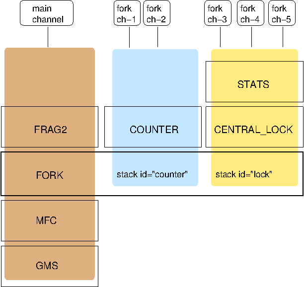
In the example, a main channel and 5 fork channels are shown. They are all running in the same JVM.
The brown stack to the left is the main stack and it has the main channel connected to it. Not all protocols are shown, but we’ve listed the GMS, MFC, FORK and FRAG2 protocols. The FORK protocol needs to be present in the main stack, or else fork stacks can not be created.
The FORK protocol of the main stack contains 2 fork stacks: "counter" and "lock". These are fork stack IDs and are used when creating a fork channel to determine whether fork channels share the same fork stack, or not.
The blue stack in the middle is a fork-stack with fork stack ID "counter". It adds protocol COUNTER to the protocols provided by the main stack. Therefore a message passing down through fork stack "counter" will pass through protocols COUNTER, FORK, MFC and GMS.
Fork channels have an ID, too, e.g. "fork-ch1". The combination of fork stack ID and fork channel ID is used to demultiplex incoming messages. For example, if fork channel 2 sends a message, it’ll pass through COUNTER and into FORK. There, a header is added to the message, containing fork channel ID="fork-ch2" and fork stack ID="counter". Then the message passes down the main stack, through MFC, GMS and so on.
When the message is received, it passes up the reverse order: first GMS, then MFC, then it is received by FORK. If there is no header, FORK passes the message up the main stack, where it passes through FRAG2 and ends up in the main channel. If a header is present, the fork stack ID is used to find the correct fork-stack ("counter"). If no fork stack is found, a warning message is logged. The message then passes through COUNTER. Finally, the fork channel ID ("fork-ch2") is used to find the right fork channel and the message is passed to it.
Note that a fork stack can have more than 1 protocol; for example the yellow fork stack on the right side has 2 protocols. A fork stack can also have 0 protocols. In that case, it is only used to have a private channel for communication, and no additional protocols are required on top of the main stack.
Fork channels sharing the same fork stack also share state. For example, fork channels fork-ch1 and fork-ch2 share COUNTER, which means they will see each other’s increments and decrements of the same counter. If fork stack "lock" also had a COUNTER protocol, and fork-ch1 anf fork-ch4 accessed a counter with the same name, they would still not see each other’s changes, as they’d have 2 different COUNTER protocols.
5.16.1. Configuration
Fork stacks can be created programmatically or declaratively. Let’s take a look at the latter first. The XML fragment below shows this:
...
<MFC max_credits="2M" min_threshold="0.4"/>
<FORK config="/home/bela/fork-stacks.xml" />
<FRAG2 frag_size="60K" />
...
FORK refers to an external file to configure its fork stacks:
<fork-stacks xmlns="fork-stacks">
    <fork-stack id="counter">
        <config>
            <COUNTER bypass_bundling="true"/>
        </config>
    </fork-stack>

    <fork-stack id="lock">
         <config>
             <CENTRAL_LOCK num_backups="2"/>
             <STATS/>
         </config>
    </fork-stack>

</fork-stacks>
The file fork-stacks.xml defines 2 fork stacks: "counter" and "lock". Each fork-stack element has an 'id' attribute which defines the fork stack’s ID. Note that all fork stacks have to have unique IDs.
After the fork-stack element, the child element starting with 'config' is a regular JGroups XML config file schema, where protocols are defined from bottom to top. For example, fork stack "lock" defines that CENTRAL_LOCK is the first protocol on top of FORK for the given fork stack, and STATS is on top of CENTRAL_LOCK.
When FORK is initialized, it will create the 2 fork stacks. When fork channels are created (see the next section), they can pick one of the 2 existing fork stacks to be created over, or they can dynamically create new fork stacks.
5.16.2. Creation of fork channels
A fork channel is created by instantiating a new ForkChannel object:
JChannel main_ch=new JChannel("/home/bela/udp.xml").name("A");
ForkChannel fork_ch=new ForkChannel(main_ch, "lock", "fork-ch4",
                                    new CENTRAL_LOCK(), new STATS());

main_ch.connect("cluster");
fork_ch.connect("bla");
First the main channel is created. Note that udp.xml may or may not contain FORK, but for this example, we assume it is present.
Then the ForkChannel is created. It is passed the main channel, the fork stack ID ("lock") and the fork channel ID ("fork-ch4"), plus a list of already instantiated protocols (CENTRAL_LOCK and STATS). If FORK already contains a fork stack with ID="lock", the existing fork stack will be used, or else a new one will be created with protocols CENTRAL_LOCK and STATS. Then a new fork channel with ID="fork-ch4" will be added to the top of fork stack "lock". An exception will be thrown if a fork channel with the same ID already exists.
The main channel then calls connect(), and - after this - the ForkChannel also calls connect(). (Note that the
latter’s connect argument (the cluster name)) is ignored as fork channels have the same cluster name as the
main channel they reference. The local address, name, view and state are also the same.
|
|
A fork channel’s connect() must be called after the main channel has been connected. If this is not the case,
ForkChannel.connect() will throw an exception.
|
The lifetime of a fork channel is always dominated by the main channel: if the main channel is closed, all fork channels atttached to it are in closed state, too, and trying to send a message will throw an exception.
The example above showed the simplified constructor, which requires the FORK protocol to be present in the stack. There’s another constructor which allows for FORK to be created dynamically if not present:
public ForkChannel(final Channel main_channel,
                   String fork_stack_id, String fork_channel_id,
                   boolean create_fork_if_absent,
                   int position,
                   Class<? extends Protocol> neighbor,
                   Protocol ... protocols) throws Exception;
In addition to passing the main channel, the fork stack and channel IDs and the list of protocols, this constructor also allows a user to create FORK in the main stack if not present. To do so, create_fork_if_absent has to be set to true (else an exception is thrown if FORK is not found), and the neighbor protocol (e.g. FRAG2.class) has to be defined, plus the position (ProtocolStack.ABOVE/BELOW) relative to the neighbor protocol has to be defined as well.
The design of FORK / ForkChannel is discussed in more detail in FORK.txt
6. List of Protocols
This chapter describes the most frequently used protocols, and their configuration. Ergonomics (Ergonomics) strives to reduce the number of properties that have to be configured, by dynamically adjusting them at run time, however, this is not yet in place.
Meanwhile, we recommend that users should copy one of the predefined configurations (shipped with JGroups), e.g. udp.xml or tcp.xml, and make only minimal changes to it.
This section is work in progress; we strive to update the documentation as we make changes to the code.
6.1. Properties available in every protocol
The table below lists properties that are available in all protocols, as they’re defined in the superclass of all protocols, org.jgroups.stack.Protocol.
| Name | Description |
|---|---|
stats |
Whether the protocol should collect protocol-specific runtime statistics. What those
statistics are (or whether they even exist) depends on the particular protocol.
See the |
ergonomics |
Turns on ergonomics. See Ergonomics for details. |
id |
Gives the protocol a different ID if needed so we can have multiple instances of it in the same stack |
after_creation_hook |
Fully qualified name of a class implementing ProtocolHook, will be called after creation of the protocol (before init()) |
preview_warning |
If true, log a warning if a protocol annotated with @Preview is used |
level |
Sets the logging level. Valid values are "fatal", "error", "warn", "info", "debug", "trace" (capitalization not relevant) |
6.2. System properties
The table below lists system properties which can be used to override attribute values, mostly in protocols. For example, if we have a config like this:
<UDP bind_addr="127.0.0.1" />, then the bind address will be 127.0.0.1. However, if we run the system with -Djgroups.bind_addr=1.2.3.4 (see below),
the bind address will be 1.2.3.4.
Note that if we use our own variables, like this:
<UDP bind_addr="${my.bind_addr:127.0.0.1}" />, then system property my.bind_addr takes precedence over jgroups.bind_addr. In the above case, the actual bind
address chosen will be:
| System properties | Bind address picked |
|---|---|
|
|
|
|
none |
|
| Name | Description |
|---|---|
|
The network interface to be used. Example: |
|
The external bind address to be used. Overrides |
|
The external port to be used by the transport. |
|
The network interface client sockets in TCP should bind to. Overrides |
|
The list of initial hosts in TCPPING |
|
The multicast address used by UDP |
|
The multicast port used by UDP |
|
The TTL used by UDP |
|
The multicast address used by MPING |
|
The multicast port used by MPING |
|
The TTL used by MPING |
|
The file where the mappings between IDs and classes are defined.
Default: |
|
The file where the mappings between IDs and protocols are defined.
Default: |
|
The max number of elements in the NameCache which holds mappings between addresses and logical names |
|
The max age (in milliseconds) a mapping between address and logical name is kept in the NameCache. Not that elements are only evicted if there’s not enough room. |
|
Needed if an IPv4 multicast address is used in an IPv6 system. The prefix (default: |
|
If true, the JDK logger ( |
|
The fully qualified name of a class implementing a logger to be used. See Logging for details. |
|
System prop for defining the default number of headers in a Message (default: |
|
Whether or not to check the version of received messages and discard them if the versions
don’t match. Default: |
6.3. Resolving names to IP addresses
The algorithm for resolving names to dotted-decimal IPv4 or IPv6 addresses is described below.
The following types of names need to be resolved:
-
Symbolic addresses such as
site_local,global,link_local,loopbackandnon_loopbacketc -
Symbolic names, e.g.
belasmac,www.google.com -
Regexps such as
match-interface,match-hostetc -
Defaults, e.g.
UDP.mcast_addr. If not set, it will be assigned228.8.8.8(IPv4) orff0e::8:8:8(IPv6)
All of these can only be resolved once we know what type of addresses we need to provide.
E.g. when UDP.bind_addr is 127.0.0.1, site_local would have to be an IPv4 address.
When bind_addr is ::1, site_local needs to pick an IPv6 address.
6.3.1. Only IPv4 stack is available
-
IPv4 addresses are created by default (e.g. by
InetAddress.getByName(), orsite_local) -
When an IPv6 address is defined in a configuration, an exception is thrown and the stack will not start
6.3.2. Only IPv6 stack is available
-
IPv6 addresses are created by default
-
When an IPv4 address is created, convert it to an IPv6-mapped address (default behavior)
6.3.3. Both IPv4 and IPv6 stacks are available (dual stack)
-
If
java.net.preferIPv4Stack=trueandjava.net.preferIPv6Addresses=false-
Assign IPv4 addresses by default
-
When an IPv6 address is encountered, throw an exception and don’t start the stack
-
-
If
java.net.preferIPv4Stack=falseandjava.net.preferIPv6Addresses=true-
Assign IPv6 addresses by default
-
When an IPv4 address is encountered, convert it to an IPv6-mapped address (default behavior)
-
-
Both
java.net.preferIPv4Stackandjava.net.preferIPv6Addressesare set, or none are set-
The JDK’s preference is to assign IPv4 addresses
-
If
bind_addris an IPv6 address → Assign IPv6 addresses -
Otherwise (or
bind_addr == null) → use IPv4 addresses
-
For dual stacks (both IPv4 and IPv6 stack is available in the JDK), these changes allow JGroups to run different configurations in the same JVM, e.g. one channel joining an IPv4 cluster, and another one joining an IPv6 cluster.
6.4. Attribute values
Attribute values are generally applied literally, after property substitution. JGroups also provides some shortcuts to specify numeric values of a certain type.
6.4.1. Size units
For numeric units indicating a size, it is possible to use the following suffixes to specify a unit of measure after the value:
-
k,kb: kilo, kilobytes (1,000 == 103) -
m,mb: mega, megabytes (1,000,000 == 106) -
g,gb: giga, gigabytes (1,000,000,000 == 109) -
kib: kibibytes (1,024 == 210) -
mib: mebibytes (1,048,576 == 220) -
gib: gibibytes (1,073,741,824 == 230)
It is also possible to use floating point numbers to indicate fractions of a unit.
Examples: 5mb, 10kib, 0.5g.
6.4.2. Time units
If an attribute is of type TIME, it is possible to use the following suffixes to specify a unit of measure after the value:
-
ms: milliseconds -
s: seconds -
m: minutes -
h: hours -
d: days
It is also possible to use floating point numbers to indicate fractions of a unit.
For example: 10m, 3s, 500ms, 1.5d.
6.5. Transport
TP is the base class for all transports, e.g. UDP and TCP. All the properties
defined here are inherited by the subclasses. The properties for TP are:
| Name | Description |
|---|---|
|
If not enabled, tasks will executed on the runner’s thread |
|
The bind address which should be used by this transport. The following special values are also recognized: GLOBAL, SITE_LOCAL, LINK_LOCAL, NON_LOOPBACK, match-interface, match-host, match-address |
|
The port to which the transport binds. Default of 0 binds to any (ephemeral) port. See also port_range |
|
The max number of messages in a bundler if the bundler supports size limitations |
|
The max number of messages in a bundler if the bundler supports size limitations |
|
The max number of messages in a bundler if the bundler supports size limitations |
|
The max number of messages in a bundler if the bundler supports size limitations |
|
The max number of messages in a bundler if the bundler supports size limitations |
|
The max number of messages in a bundler if the bundler supports size limitations |
|
When true, when there’s no space to queue a message, senders will drop the message ratherthan wait until space is available (https://issues.redhat.com/browse/JGRP-2765) |
|
When true, when there’s no space to queue a message, senders will drop the message ratherthan wait until space is available (https://issues.redhat.com/browse/JGRP-2765) |
|
When true, when there’s no space to queue a message, senders will drop the message ratherthan wait until space is available (https://issues.redhat.com/browse/JGRP-2765) |
|
When true, when there’s no space to queue a message, senders will drop the message ratherthan wait until space is available (https://issues.redhat.com/browse/JGRP-2765) |
|
When true, when there’s no space to queue a message, senders will drop the message ratherthan wait until space is available (https://issues.redhat.com/browse/JGRP-2765) |
|
When true, when there’s no space to queue a message, senders will drop the message ratherthan wait until space is available (https://issues.redhat.com/browse/JGRP-2765) |
|
Maximum number of bytes for messages to be queued until they are sent |
|
Maximum number of bytes for messages to be queued until they are sent |
|
Maximum number of bytes for messages to be queued until they are sent |
|
Maximum number of bytes for messages to be queued until they are sent |
|
Maximum number of bytes for messages to be queued until they are sent |
|
Maximum number of bytes for messages to be queued until they are sent |
|
Delay (in ms) after which queued messages to non-members are removed |
|
Delay (in ms) after which queued messages to non-members are removed |
|
Delay (in ms) after which queued messages to non-members are removed |
|
Delay (in ms) after which queued messages to non-members are removed |
|
Delay (in ms) after which queued messages to non-members are removed |
|
Delay (in ms) after which queued messages to non-members are removed |
|
Capacity of the remove queue. If > 0, the capacity is fixed, otherwise it will be computed dynamically as a function of capacity |
|
Capacity of the remove queue. If > 0, the capacity is fixed, otherwise it will be computed dynamically as a function of capacity |
|
Capacity of the remove queue. If > 0, the capacity is fixed, otherwise it will be computed dynamically as a function of capacity |
|
Capacity of the remove queue. If > 0, the capacity is fixed, otherwise it will be computed dynamically as a function of capacity |
|
Capacity of the remove queue. If > 0, the capacity is fixed, otherwise it will be computed dynamically as a function of capacity |
|
Capacity of the remove queue. If > 0, the capacity is fixed, otherwise it will be computed dynamically as a function of capacity |
|
Number of milliseconds duplicate warnings (e.g. connection/sending failed) should be suppressed. 0 disables the suppress log |
|
Number of milliseconds duplicate warnings (e.g. connection/sending failed) should be suppressed. 0 disables the suppress log |
|
Number of milliseconds duplicate warnings (e.g. connection/sending failed) should be suppressed. 0 disables the suppress log |
|
Number of milliseconds duplicate warnings (e.g. connection/sending failed) should be suppressed. 0 disables the suppress log |
|
Number of milliseconds duplicate warnings (e.g. connection/sending failed) should be suppressed. 0 disables the suppress log |
|
Number of milliseconds duplicate warnings (e.g. connection/sending failed) should be suppressed. 0 disables the suppress log |
|
True: the queues (e.g. TransferQueueBundler, PerDestinationBundler) use ConcurrentBlockingRingBuffer. False: they use ConcurrentLinkedBlockingQueue. Bundlers may ignore this attribute |
|
True: the queues (e.g. TransferQueueBundler, PerDestinationBundler) use ConcurrentBlockingRingBuffer. False: they use ConcurrentLinkedBlockingQueue. Bundlers may ignore this attribute |
|
True: the queues (e.g. TransferQueueBundler, PerDestinationBundler) use ConcurrentBlockingRingBuffer. False: they use ConcurrentLinkedBlockingQueue. Bundlers may ignore this attribute |
|
True: the queues (e.g. TransferQueueBundler, PerDestinationBundler) use ConcurrentBlockingRingBuffer. False: they use ConcurrentLinkedBlockingQueue. Bundlers may ignore this attribute |
|
True: the queues (e.g. TransferQueueBundler, PerDestinationBundler) use ConcurrentBlockingRingBuffer. False: they use ConcurrentLinkedBlockingQueue. Bundlers may ignore this attribute |
|
True: the queues (e.g. TransferQueueBundler, PerDestinationBundler) use ConcurrentBlockingRingBuffer. False: they use ConcurrentLinkedBlockingQueue. Bundlers may ignore this attribute |
|
True: use a single thread for all destinationns. False: use a thread per destination. This is currently only used by PerDestinationBundler, but was hoisted into the base class so the same configuration could be used when changing bundlers |
|
True: use a single thread for all destinationns. False: use a thread per destination. This is currently only used by PerDestinationBundler, but was hoisted into the base class so the same configuration could be used when changing bundlers |
|
True: use a single thread for all destinationns. False: use a thread per destination. This is currently only used by PerDestinationBundler, but was hoisted into the base class so the same configuration could be used when changing bundlers |
|
True: use a single thread for all destinationns. False: use a thread per destination. This is currently only used by PerDestinationBundler, but was hoisted into the base class so the same configuration could be used when changing bundlers |
|
True: use a single thread for all destinationns. False: use a thread per destination. This is currently only used by PerDestinationBundler, but was hoisted into the base class so the same configuration could be used when changing bundlers |
|
True: use a single thread for all destinationns. False: use a thread per destination. This is currently only used by PerDestinationBundler, but was hoisted into the base class so the same configuration could be used when changing bundlers |
|
The type of bundler used ("ring-buffer", "transfer-queue" (default), "sender-sends" or "no-bundler") or the fully qualified classname of a Bundler implementation |
|
Bind address for diagnostic probing, to bind the TCP socket. Used when enable_tcp is true |
|
Comma delimited list of interfaces (IP addrs or interface names) that the multicast socket should bind to |
|
Use a TCP socket to listen for probe requests (ignored if diag.enabled is false) |
|
Use a multicast socket to listen for probe requests (ignored if diag.enabled is false) |
|
Switch to enable diagnostic probing |
|
Multicast address for diagnostic probing (UDP MulticastSocket). Used when enable_udp is true |
|
Authorization passcode for diagnostics. If specified every probe query will be authorized |
|
Port for diagnostic probing. Default is 7500 |
|
The number of ports to be probed for an available port (TCP) |
|
TTL of the diagnostics multicast socket |
|
Enables or disables RTT functionality |
|
Use "external_addr" if you have hosts on different networks, behind firewalls. On each firewall, set up a port forwarding rule (sometimes called "virtual server") to the local IP (e.g. 192.168.1.100) of the host then on each host, set "external_addr" TCP transport parameter to the external (public IP) address of the firewall. |
|
Used to map the internal port (bind_port) to an external port. Only used if > 0 |
|
The fully qualified name of a class implementing LocalTransport |
|
whether or not warnings about messages from different groups are logged |
|
whether or not warnings about messages from members with a different version are discarded |
|
Time (in ms) after which entries in the logical address cache marked as removable and can be removed. 0 never removes any entries (not recommended) |
|
Max number of elements in the logical address cache before eviction starts |
|
Interval (in ms) at which the reaper task scans logical_addr_cache and removes entries marked as removable. 0 disables reaping. |
|
The fully qualified name of a class implementing MessageProcessingPolicy |
|
Max number of messages buffered for consumption of the delivery thread in MaxOneThreadPerSender. 0 creates an unbounded buffer |
|
Max number of messages buffered for consumption of the delivery thread in MaxOneThreadPerSender. 0 creates an unbounded buffer |
|
If > 0, then batches > max_size will be unbatched, batches ⇐ max_size will be sent up. This ensures that no batch will ever be greater than a given size. |
|
Whether metrics should be logged |
|
The number of RPCs to send |
|
Send requests and responses as OOB messages |
|
The range of valid ports: [bind_port .. bind_port+port_range ]. 0 only binds to bind_port and fails if taken |
|
Comma delimited list of interfaces (IP addresses or interface names) to receive multicasts on |
|
If true, the transport should use all available interfaces to receive multicast messages |
|
Size (in bytes) of an RPC |
|
Time during which identical warnings about messages from a member from a different cluster will be suppressed. 0 disables this (every warning will be logged). Setting the log level to ERROR also disables this. |
|
Time during which identical warnings about messages from a member with a different version will be suppressed. 0 disables this (every warning will be logged). Setting the log level to ERROR also disables this. |
|
Thread naming pattern for threads in this channel. Valid values are "cl": "c": includes the cluster name, e.g. "MyCluster", "l": includes the local address of the current member, e.g. "A" |
|
If the view is greater than the max thread pool size, the latter is set to view size + delta. Only enabled if increase_max_size_dynamically is true |
|
Whether or not the thread pool is enabled. If false, tasks will be run on the caller’s thread |
|
Increases max_threads by the view size + delta if enabled (https://issues.redhat.com/browse/JGRP-2655) |
|
Timeout (ms) to remove idle threads from the pool |
|
Maximum thread pool size for the thread pool |
|
Minimum thread pool size for the thread pool |
|
The rejection policy to be used in the thread pool (abort, discard, run, custom etc. See Util.parseRejectionPolicy() for details |
|
Path to which the thread dump will be written. Ignored if null |
|
Dump threads when the thread pool is full |
|
The number of times a thread pool needs to be full before a thread dump is logged |
|
Time (in milliseconds) during which thread-pool full messages are suppressed |
|
Interval (in ms) at which the time service updates its timestamp. 0 disables the time service |
|
Timeout (ms) for an RPC |
|
If true, create virtual threads, otherwise create native threads |
|
Timeout (in ms) to determine how long to wait until a request to fetch the physical address for a given logical address will be sent again. Subsequent requests for the same physical address will therefore be spaced at least who_has_cache_timeout ms apart |
bind_addr can be set to the address of a network interface, e.g. 192.168.1.5.
It can also be set for the entire stack using system property -Djgroups.bind_addr, which
provides a value for bind_addr unless it has already been set in the XML config.
The following special values are also recognized for bind_addr:
- GLOBAL
-
Picks a global IP address if available. If not, falls back to a SITE_LOCAL IP address.
- SITE_LOCAL
-
Picks a site local (non-routable) IP address, e.g. from the
192.168.0.0or10.0.0.0address range. - use-localhost
-
Returns the result of calling
InetAddress.getLocalHost(). - LINK_LOCAL
-
Picks a link-local IP address, from
169.254.1.0through169.254.254.255. - NON_LOOPBACK
-
Picks any non loopback address.
- LOOPBACK
-
Pick a loopback address, e.g.
127.0.0.1. - match-interface
-
Pick an address which matches a pattern against the interface name, e.g.
match-interface:eth.\* - match-address
-
Pick an address which matches a pattern against the host address, e.g.
match-address:192.168.\* - match-host
-
Pick an address which matches a pattern against the host name, e.g.
match-host:linux.\* - custom
-
Use custom code to pick the bind address. The value after
customneeds to be the fully qualified name of a class implementingSupplier<InetAddress>, e.g. bind_addr="custom:com.acme.BindAddressPicker".
An example of setting the bind address in UDP to use a site local address is:
<UDP bind_addr="SITE_LOCAL" />This will pick any address of any interface that’s site-local, e.g. a 192.168.x.x or 10.x.x.x address.
Since 4.0, it is possible to define a list of addresses in bind_addr. Each entry of the list will be tried and the
first entry that works will be used. Example:
<UDP bind_addr="match-interface:eth2,10.5.5.5,match-interface:en.\*,127.0.0.1" />This would try to bind to eth2 first. If not found, then an interface with address 10.5.5.5 would be tried,
then an interface starting with en would be tried. If still not found, we’d bind to 127.0.0.1.
Details of how IPv4 versus IPv6 addresses are picked can be found in https://issues.redhat.com/browse/JGRP-2343.
6.5.1. UDP
UDP uses IP multicast for sending messages to all members of a group and UDP datagrams for unicast messages (sent to a single member). When started, it opens a unicast and multicast socket: the unicast socket is used to send/receive unicast messages, whereas the multicast socket sends and receives multicast messages. The channel’s physical address will be the address and port number of the unicast socket.
A protocol stack with UDP as transport protocol is typically used with clusters whose members run in the same subnet. If running across subnets, an admin has to ensure that IP multicast is enabled across subnets. It is often the case that IP multicast is not enabled across subnets. In such cases, the stack has to either use UDP without IP multicasting or other transports such as TCP.
| Name | Description |
|---|---|
|
If not enabled, tasks will executed on the runner’s thread |
|
The bind address which should be used by this transport. The following special values are also recognized: GLOBAL, SITE_LOCAL, LINK_LOCAL, NON_LOOPBACK, match-interface, match-host, match-address |
|
The port to which the transport binds. Default of 0 binds to any (ephemeral) port. See also port_range |
|
The max number of messages in a bundler if the bundler supports size limitations |
|
The max number of messages in a bundler if the bundler supports size limitations |
|
The max number of messages in a bundler if the bundler supports size limitations |
|
The max number of messages in a bundler if the bundler supports size limitations |
|
The max number of messages in a bundler if the bundler supports size limitations |
|
The max number of messages in a bundler if the bundler supports size limitations |
|
When true, when there’s no space to queue a message, senders will drop the message ratherthan wait until space is available (https://issues.redhat.com/browse/JGRP-2765) |
|
When true, when there’s no space to queue a message, senders will drop the message ratherthan wait until space is available (https://issues.redhat.com/browse/JGRP-2765) |
|
When true, when there’s no space to queue a message, senders will drop the message ratherthan wait until space is available (https://issues.redhat.com/browse/JGRP-2765) |
|
When true, when there’s no space to queue a message, senders will drop the message ratherthan wait until space is available (https://issues.redhat.com/browse/JGRP-2765) |
|
When true, when there’s no space to queue a message, senders will drop the message ratherthan wait until space is available (https://issues.redhat.com/browse/JGRP-2765) |
|
When true, when there’s no space to queue a message, senders will drop the message ratherthan wait until space is available (https://issues.redhat.com/browse/JGRP-2765) |
|
Maximum number of bytes for messages to be queued until they are sent |
|
Maximum number of bytes for messages to be queued until they are sent |
|
Maximum number of bytes for messages to be queued until they are sent |
|
Maximum number of bytes for messages to be queued until they are sent |
|
Maximum number of bytes for messages to be queued until they are sent |
|
Maximum number of bytes for messages to be queued until they are sent |
|
Delay (in ms) after which queued messages to non-members are removed |
|
Delay (in ms) after which queued messages to non-members are removed |
|
Delay (in ms) after which queued messages to non-members are removed |
|
Delay (in ms) after which queued messages to non-members are removed |
|
Delay (in ms) after which queued messages to non-members are removed |
|
Delay (in ms) after which queued messages to non-members are removed |
|
Capacity of the remove queue. If > 0, the capacity is fixed, otherwise it will be computed dynamically as a function of capacity |
|
Capacity of the remove queue. If > 0, the capacity is fixed, otherwise it will be computed dynamically as a function of capacity |
|
Capacity of the remove queue. If > 0, the capacity is fixed, otherwise it will be computed dynamically as a function of capacity |
|
Capacity of the remove queue. If > 0, the capacity is fixed, otherwise it will be computed dynamically as a function of capacity |
|
Capacity of the remove queue. If > 0, the capacity is fixed, otherwise it will be computed dynamically as a function of capacity |
|
Capacity of the remove queue. If > 0, the capacity is fixed, otherwise it will be computed dynamically as a function of capacity |
|
Number of milliseconds duplicate warnings (e.g. connection/sending failed) should be suppressed. 0 disables the suppress log |
|
Number of milliseconds duplicate warnings (e.g. connection/sending failed) should be suppressed. 0 disables the suppress log |
|
Number of milliseconds duplicate warnings (e.g. connection/sending failed) should be suppressed. 0 disables the suppress log |
|
Number of milliseconds duplicate warnings (e.g. connection/sending failed) should be suppressed. 0 disables the suppress log |
|
Number of milliseconds duplicate warnings (e.g. connection/sending failed) should be suppressed. 0 disables the suppress log |
|
Number of milliseconds duplicate warnings (e.g. connection/sending failed) should be suppressed. 0 disables the suppress log |
|
True: the queues (e.g. TransferQueueBundler, PerDestinationBundler) use ConcurrentBlockingRingBuffer. False: they use ConcurrentLinkedBlockingQueue. Bundlers may ignore this attribute |
|
True: the queues (e.g. TransferQueueBundler, PerDestinationBundler) use ConcurrentBlockingRingBuffer. False: they use ConcurrentLinkedBlockingQueue. Bundlers may ignore this attribute |
|
True: the queues (e.g. TransferQueueBundler, PerDestinationBundler) use ConcurrentBlockingRingBuffer. False: they use ConcurrentLinkedBlockingQueue. Bundlers may ignore this attribute |
|
True: the queues (e.g. TransferQueueBundler, PerDestinationBundler) use ConcurrentBlockingRingBuffer. False: they use ConcurrentLinkedBlockingQueue. Bundlers may ignore this attribute |
|
True: the queues (e.g. TransferQueueBundler, PerDestinationBundler) use ConcurrentBlockingRingBuffer. False: they use ConcurrentLinkedBlockingQueue. Bundlers may ignore this attribute |
|
True: the queues (e.g. TransferQueueBundler, PerDestinationBundler) use ConcurrentBlockingRingBuffer. False: they use ConcurrentLinkedBlockingQueue. Bundlers may ignore this attribute |
|
True: use a single thread for all destinationns. False: use a thread per destination. This is currently only used by PerDestinationBundler, but was hoisted into the base class so the same configuration could be used when changing bundlers |
|
True: use a single thread for all destinationns. False: use a thread per destination. This is currently only used by PerDestinationBundler, but was hoisted into the base class so the same configuration could be used when changing bundlers |
|
True: use a single thread for all destinationns. False: use a thread per destination. This is currently only used by PerDestinationBundler, but was hoisted into the base class so the same configuration could be used when changing bundlers |
|
True: use a single thread for all destinationns. False: use a thread per destination. This is currently only used by PerDestinationBundler, but was hoisted into the base class so the same configuration could be used when changing bundlers |
|
True: use a single thread for all destinationns. False: use a thread per destination. This is currently only used by PerDestinationBundler, but was hoisted into the base class so the same configuration could be used when changing bundlers |
|
True: use a single thread for all destinationns. False: use a thread per destination. This is currently only used by PerDestinationBundler, but was hoisted into the base class so the same configuration could be used when changing bundlers |
|
The type of bundler used ("ring-buffer", "transfer-queue" (default), "sender-sends" or "no-bundler") or the fully qualified classname of a Bundler implementation |
|
Bind address for diagnostic probing, to bind the TCP socket. Used when enable_tcp is true |
|
Comma delimited list of interfaces (IP addrs or interface names) that the multicast socket should bind to |
|
Use a TCP socket to listen for probe requests (ignored if diag.enabled is false) |
|
Use a multicast socket to listen for probe requests (ignored if diag.enabled is false) |
|
Switch to enable diagnostic probing |
|
Multicast address for diagnostic probing (UDP MulticastSocket). Used when enable_udp is true |
|
Authorization passcode for diagnostics. If specified every probe query will be authorized |
|
Port for diagnostic probing. Default is 7500 |
|
The number of ports to be probed for an available port (TCP) |
|
TTL of the diagnostics multicast socket |
|
If true, disables IP_MULTICAST_LOOP on the MulticastSocket (for sending and receiving of multicast packets). IP multicast packets send on a host P will therefore not be received by anyone on P. Use with caution. |
|
Enables or disables RTT functionality |
|
Use "external_addr" if you have hosts on different networks, behind firewalls. On each firewall, set up a port forwarding rule (sometimes called "virtual server") to the local IP (e.g. 192.168.1.100) of the host then on each host, set "external_addr" TCP transport parameter to the external (public IP) address of the firewall. |
|
Used to map the internal port (bind_port) to an external port. Only used if > 0 |
|
Multicast toggle. If false multiple unicast datagrams are sent instead of one multicast. Default is true |
|
The time-to-live (TTL) for multicast datagram packets. Default is 8 |
|
The fully qualified name of a class implementing LocalTransport |
|
whether or not warnings about messages from different groups are logged |
|
whether or not warnings about messages from members with a different version are discarded |
|
Time (in ms) after which entries in the logical address cache marked as removable and can be removed. 0 never removes any entries (not recommended) |
|
Max number of elements in the logical address cache before eviction starts |
|
Interval (in ms) at which the reaper task scans logical_addr_cache and removes entries marked as removable. 0 disables reaping. |
|
The multicast address used for sending and receiving packets |
|
The multicast port used for sending and receiving packets. Default is 7600 |
|
Number of multicast receiver threads, all reading from the same MulticastSocket. If de-serialization is slow, increasing the number of receiver threads might yield better performance. |
|
Receive buffer size of the multicast datagram socket |
|
Send buffer size of the multicast datagram socket |
|
The fully qualified name of a class implementing MessageProcessingPolicy |
|
Max number of messages buffered for consumption of the delivery thread in MaxOneThreadPerSender. 0 creates an unbounded buffer |
|
Max number of messages buffered for consumption of the delivery thread in MaxOneThreadPerSender. 0 creates an unbounded buffer |
|
If > 0, then batches > max_size will be unbatched, batches ⇐ max_size will be sent up. This ensures that no batch will ever be greater than a given size. |
|
Whether metrics should be logged |
|
The number of RPCs to send |
|
Send requests and responses as OOB messages |
|
The range of valid ports: [bind_port .. bind_port+port_range ]. 0 only binds to bind_port and fails if taken |
|
Comma delimited list of interfaces (IP addresses or interface names) to receive multicasts on |
|
If true, the transport should use all available interfaces to receive multicast messages |
|
Size (in bytes) of an RPC |
|
Time during which identical warnings about messages from a member from a different cluster will be suppressed. 0 disables this (every warning will be logged). Setting the log level to ERROR also disables this. |
|
Time during which identical warnings about messages from a member with a different version will be suppressed. 0 disables this (every warning will be logged). Setting the log level to ERROR also disables this. |
|
Suppresses warnings on Mac OS (for now) about not enough buffer space when sending a datagram packet |
|
Thread naming pattern for threads in this channel. Valid values are "cl": "c": includes the cluster name, e.g. "MyCluster", "l": includes the local address of the current member, e.g. "A" |
|
If the view is greater than the max thread pool size, the latter is set to view size + delta. Only enabled if increase_max_size_dynamically is true |
|
Whether or not the thread pool is enabled. If false, tasks will be run on the caller’s thread |
|
Increases max_threads by the view size + delta if enabled (https://issues.redhat.com/browse/JGRP-2655) |
|
Timeout (ms) to remove idle threads from the pool |
|
Maximum thread pool size for the thread pool |
|
Minimum thread pool size for the thread pool |
|
The rejection policy to be used in the thread pool (abort, discard, run, custom etc. See Util.parseRejectionPolicy() for details |
|
Path to which the thread dump will be written. Ignored if null |
|
Dump threads when the thread pool is full |
|
The number of times a thread pool needs to be full before a thread dump is logged |
|
Time (in milliseconds) during which thread-pool full messages are suppressed |
|
Interval (in ms) at which the time service updates its timestamp. 0 disables the time service |
|
Timeout (ms) for an RPC |
|
Traffic class for sending unicast and multicast datagrams |
|
Number of unicast receiver threads, all reading from the same DatagramSocket. If de-serialization is slow, increasing the number of receiver threads might yield better performance. |
|
Receive buffer size of the unicast datagram socket |
|
Send buffer size of the unicast datagram socket |
|
If true, create virtual threads, otherwise create native threads |
|
Timeout (in ms) to determine how long to wait until a request to fetch the physical address for a given logical address will be sent again. Subsequent requests for the same physical address will therefore be spaced at least who_has_cache_timeout ms apart |
6.5.2. TCP
Specifying TCP in your protocol stack tells JGroups to use TCP to send messages between cluster members. Instead of using a multicast bus, the cluster members create a mesh of TCP connections.
For example, while UDP sends 1 IP multicast packet when sending a message to a cluster of 10 members, TCP needs to send the message 9 times. It sends the same message to the first member, to the second member, and so on (excluding itself as the message is looped back internally).
This is slow, as the cost of sending a group message is O(N-1) with TCP, where it is O(1) with UDP. As the cost of sending a group message with TCP is a function of the cluster size, it becomes higher with larger clusters.
|
|
We recommend to use UDP for larger clusters, whenever possible |
| Name | Description |
|---|---|
|
If not enabled, tasks will executed on the runner’s thread |
|
The bind address which should be used by this transport. The following special values are also recognized: GLOBAL, SITE_LOCAL, LINK_LOCAL, NON_LOOPBACK, match-interface, match-host, match-address |
|
The port to which the transport binds. Default of 0 binds to any (ephemeral) port. See also port_range |
|
The max number of messages in a bundler if the bundler supports size limitations |
|
The max number of messages in a bundler if the bundler supports size limitations |
|
The max number of messages in a bundler if the bundler supports size limitations |
|
The max number of messages in a bundler if the bundler supports size limitations |
|
The max number of messages in a bundler if the bundler supports size limitations |
|
The max number of messages in a bundler if the bundler supports size limitations |
|
When true, when there’s no space to queue a message, senders will drop the message ratherthan wait until space is available (https://issues.redhat.com/browse/JGRP-2765) |
|
When true, when there’s no space to queue a message, senders will drop the message ratherthan wait until space is available (https://issues.redhat.com/browse/JGRP-2765) |
|
When true, when there’s no space to queue a message, senders will drop the message ratherthan wait until space is available (https://issues.redhat.com/browse/JGRP-2765) |
|
When true, when there’s no space to queue a message, senders will drop the message ratherthan wait until space is available (https://issues.redhat.com/browse/JGRP-2765) |
|
When true, when there’s no space to queue a message, senders will drop the message ratherthan wait until space is available (https://issues.redhat.com/browse/JGRP-2765) |
|
When true, when there’s no space to queue a message, senders will drop the message ratherthan wait until space is available (https://issues.redhat.com/browse/JGRP-2765) |
|
Maximum number of bytes for messages to be queued until they are sent |
|
Maximum number of bytes for messages to be queued until they are sent |
|
Maximum number of bytes for messages to be queued until they are sent |
|
Maximum number of bytes for messages to be queued until they are sent |
|
Maximum number of bytes for messages to be queued until they are sent |
|
Maximum number of bytes for messages to be queued until they are sent |
|
Delay (in ms) after which queued messages to non-members are removed |
|
Delay (in ms) after which queued messages to non-members are removed |
|
Delay (in ms) after which queued messages to non-members are removed |
|
Delay (in ms) after which queued messages to non-members are removed |
|
Delay (in ms) after which queued messages to non-members are removed |
|
Delay (in ms) after which queued messages to non-members are removed |
|
Capacity of the remove queue. If > 0, the capacity is fixed, otherwise it will be computed dynamically as a function of capacity |
|
Capacity of the remove queue. If > 0, the capacity is fixed, otherwise it will be computed dynamically as a function of capacity |
|
Capacity of the remove queue. If > 0, the capacity is fixed, otherwise it will be computed dynamically as a function of capacity |
|
Capacity of the remove queue. If > 0, the capacity is fixed, otherwise it will be computed dynamically as a function of capacity |
|
Capacity of the remove queue. If > 0, the capacity is fixed, otherwise it will be computed dynamically as a function of capacity |
|
Capacity of the remove queue. If > 0, the capacity is fixed, otherwise it will be computed dynamically as a function of capacity |
|
Number of milliseconds duplicate warnings (e.g. connection/sending failed) should be suppressed. 0 disables the suppress log |
|
Number of milliseconds duplicate warnings (e.g. connection/sending failed) should be suppressed. 0 disables the suppress log |
|
Number of milliseconds duplicate warnings (e.g. connection/sending failed) should be suppressed. 0 disables the suppress log |
|
Number of milliseconds duplicate warnings (e.g. connection/sending failed) should be suppressed. 0 disables the suppress log |
|
Number of milliseconds duplicate warnings (e.g. connection/sending failed) should be suppressed. 0 disables the suppress log |
|
Number of milliseconds duplicate warnings (e.g. connection/sending failed) should be suppressed. 0 disables the suppress log |
|
True: the queues (e.g. TransferQueueBundler, PerDestinationBundler) use ConcurrentBlockingRingBuffer. False: they use ConcurrentLinkedBlockingQueue. Bundlers may ignore this attribute |
|
True: the queues (e.g. TransferQueueBundler, PerDestinationBundler) use ConcurrentBlockingRingBuffer. False: they use ConcurrentLinkedBlockingQueue. Bundlers may ignore this attribute |
|
True: the queues (e.g. TransferQueueBundler, PerDestinationBundler) use ConcurrentBlockingRingBuffer. False: they use ConcurrentLinkedBlockingQueue. Bundlers may ignore this attribute |
|
True: the queues (e.g. TransferQueueBundler, PerDestinationBundler) use ConcurrentBlockingRingBuffer. False: they use ConcurrentLinkedBlockingQueue. Bundlers may ignore this attribute |
|
True: the queues (e.g. TransferQueueBundler, PerDestinationBundler) use ConcurrentBlockingRingBuffer. False: they use ConcurrentLinkedBlockingQueue. Bundlers may ignore this attribute |
|
True: the queues (e.g. TransferQueueBundler, PerDestinationBundler) use ConcurrentBlockingRingBuffer. False: they use ConcurrentLinkedBlockingQueue. Bundlers may ignore this attribute |
|
True: use a single thread for all destinationns. False: use a thread per destination. This is currently only used by PerDestinationBundler, but was hoisted into the base class so the same configuration could be used when changing bundlers |
|
True: use a single thread for all destinationns. False: use a thread per destination. This is currently only used by PerDestinationBundler, but was hoisted into the base class so the same configuration could be used when changing bundlers |
|
True: use a single thread for all destinationns. False: use a thread per destination. This is currently only used by PerDestinationBundler, but was hoisted into the base class so the same configuration could be used when changing bundlers |
|
True: use a single thread for all destinationns. False: use a thread per destination. This is currently only used by PerDestinationBundler, but was hoisted into the base class so the same configuration could be used when changing bundlers |
|
True: use a single thread for all destinationns. False: use a thread per destination. This is currently only used by PerDestinationBundler, but was hoisted into the base class so the same configuration could be used when changing bundlers |
|
True: use a single thread for all destinationns. False: use a thread per destination. This is currently only used by PerDestinationBundler, but was hoisted into the base class so the same configuration could be used when changing bundlers |
|
The type of bundler used ("ring-buffer", "transfer-queue" (default), "sender-sends" or "no-bundler") or the fully qualified classname of a Bundler implementation |
|
The address of a local network interface which should be used by client sockets to bind to. The following special values are also recognized: GLOBAL, SITE_LOCAL, LINK_LOCAL and NON_LOOPBACK |
|
The local port a client socket should bind to. If 0, an ephemeral port will be picked. |
|
Max time connection can be idle before being reaped (in ms) |
|
If true, client sockets will not explicitly bind to bind_addr but will defer to the native socket |
|
Bind address for diagnostic probing, to bind the TCP socket. Used when enable_tcp is true |
|
Comma delimited list of interfaces (IP addrs or interface names) that the multicast socket should bind to |
|
Use a TCP socket to listen for probe requests (ignored if diag.enabled is false) |
|
Use a multicast socket to listen for probe requests (ignored if diag.enabled is false) |
|
Switch to enable diagnostic probing |
|
Multicast address for diagnostic probing (UDP MulticastSocket). Used when enable_udp is true |
|
Authorization passcode for diagnostics. If specified every probe query will be authorized |
|
Port for diagnostic probing. Default is 7500 |
|
The number of ports to be probed for an available port (TCP) |
|
TTL of the diagnostics multicast socket |
|
When true, a SUSPECT(P) event is passed up when a connection is closed by the peer P. https://issues.redhat.com/browse/JGRP-2869 |
|
Enables or disables RTT functionality |
|
Use "external_addr" if you have hosts on different networks, behind firewalls. On each firewall, set up a port forwarding rule (sometimes called "virtual server") to the local IP (e.g. 192.168.1.100) of the host then on each host, set "external_addr" TCP transport parameter to the external (public IP) address of the firewall. |
|
Used to map the internal port (bind_port) to an external port. Only used if > 0 |
|
SO_LINGER in seconds. Default of -1 disables it |
|
The fully qualified name of a class implementing LocalTransport |
|
Log a stack trace when a connection is closed |
|
whether or not warnings about messages from different groups are logged |
|
whether or not warnings about messages from members with a different version are discarded |
|
Time (in ms) after which entries in the logical address cache marked as removable and can be removed. 0 never removes any entries (not recommended) |
|
Max number of elements in the logical address cache before eviction starts |
|
Interval (in ms) at which the reaper task scans logical_addr_cache and removes entries marked as removable. 0 disables reaping. |
|
The max number of bytes a message can have. If greater, an exception will be thrown. 0 disables this |
|
The fully qualified name of a class implementing MessageProcessingPolicy |
|
Max number of messages buffered for consumption of the delivery thread in MaxOneThreadPerSender. 0 creates an unbounded buffer |
|
Max number of messages buffered for consumption of the delivery thread in MaxOneThreadPerSender. 0 creates an unbounded buffer |
|
If > 0, then batches > max_size will be unbatched, batches ⇐ max_size will be sent up. This ensures that no batch will ever be greater than a given size. |
|
Whether metrics should be logged |
|
The number of RPCs to send |
|
Send requests and responses as OOB messages |
|
Max time to block on reading of peer address |
|
The range of valid ports: [bind_port .. bind_port+port_range ]. 0 only binds to bind_port and fails if taken |
|
Reaper interval in msec. Default is 0 (no reaping) |
|
Comma delimited list of interfaces (IP addresses or interface names) to receive multicasts on |
|
If true, the transport should use all available interfaces to receive multicast messages |
|
Receiver buffer size in bytes |
|
Send buffer size in bytes |
|
Size (in bytes) of an RPC |
|
Max time allowed for a socket creation in connection table |
|
Time during which identical warnings about messages from a member from a different cluster will be suppressed. 0 disables this (every warning will be logged). Setting the log level to ERROR also disables this. |
|
Time during which identical warnings about messages from a member with a different version will be suppressed. 0 disables this (every warning will be logged). Setting the log level to ERROR also disables this. |
|
Should TCP no delay flag be turned on. True: nagling is OFF, false: nagling is ON |
|
Thread naming pattern for threads in this channel. Valid values are "cl": "c": includes the cluster name, e.g. "MyCluster", "l": includes the local address of the current member, e.g. "A" |
|
If the view is greater than the max thread pool size, the latter is set to view size + delta. Only enabled if increase_max_size_dynamically is true |
|
Whether or not the thread pool is enabled. If false, tasks will be run on the caller’s thread |
|
Increases max_threads by the view size + delta if enabled (https://issues.redhat.com/browse/JGRP-2655) |
|
Timeout (ms) to remove idle threads from the pool |
|
Maximum thread pool size for the thread pool |
|
Minimum thread pool size for the thread pool |
|
The rejection policy to be used in the thread pool (abort, discard, run, custom etc. See Util.parseRejectionPolicy() for details |
|
Path to which the thread dump will be written. Ignored if null |
|
Dump threads when the thread pool is full |
|
The number of times a thread pool needs to be full before a thread dump is logged |
|
Time (in milliseconds) during which thread-pool full messages are suppressed |
|
Interval (in ms) at which the time service updates its timestamp. 0 disables the time service |
|
Timeout (ms) for an RPC |
|
Wait for an ack from the server when a connection is established (https://issues.redhat.com/browse/JGRP-2684) |
|
If true, create virtual threads, otherwise create native threads |
|
Timeout (in ms) to determine how long to wait until a request to fetch the physical address for a given logical address will be sent again. Subsequent requests for the same physical address will therefore be spaced at least who_has_cache_timeout ms apart |
| Name | Description |
|---|---|
|
If not enabled, tasks will executed on the runner’s thread |
|
The bind address which should be used by this transport. The following special values are also recognized: GLOBAL, SITE_LOCAL, LINK_LOCAL, NON_LOOPBACK, match-interface, match-host, match-address |
|
The port to which the transport binds. Default of 0 binds to any (ephemeral) port. See also port_range |
|
Size of the buffer of the BufferedInputStream in TcpConnection. A read always tries to read ahead as much data as possible into the buffer. 0: default size |
|
Size of the buffer of the BufferedOutputStream in TcpConnection. Smaller messages are buffered until this size is exceeded or flush() is called. Bigger messages are sent immediately. A value of 0 skips creation of the BufferedOutputStream: messages are sent directly to the socket’s output stream |
|
The max number of messages in a bundler if the bundler supports size limitations |
|
The max number of messages in a bundler if the bundler supports size limitations |
|
The max number of messages in a bundler if the bundler supports size limitations |
|
The max number of messages in a bundler if the bundler supports size limitations |
|
The max number of messages in a bundler if the bundler supports size limitations |
|
The max number of messages in a bundler if the bundler supports size limitations |
|
When true, when there’s no space to queue a message, senders will drop the message ratherthan wait until space is available (https://issues.redhat.com/browse/JGRP-2765) |
|
When true, when there’s no space to queue a message, senders will drop the message ratherthan wait until space is available (https://issues.redhat.com/browse/JGRP-2765) |
|
When true, when there’s no space to queue a message, senders will drop the message ratherthan wait until space is available (https://issues.redhat.com/browse/JGRP-2765) |
|
When true, when there’s no space to queue a message, senders will drop the message ratherthan wait until space is available (https://issues.redhat.com/browse/JGRP-2765) |
|
When true, when there’s no space to queue a message, senders will drop the message ratherthan wait until space is available (https://issues.redhat.com/browse/JGRP-2765) |
|
When true, when there’s no space to queue a message, senders will drop the message ratherthan wait until space is available (https://issues.redhat.com/browse/JGRP-2765) |
|
Maximum number of bytes for messages to be queued until they are sent |
|
Maximum number of bytes for messages to be queued until they are sent |
|
Maximum number of bytes for messages to be queued until they are sent |
|
Maximum number of bytes for messages to be queued until they are sent |
|
Maximum number of bytes for messages to be queued until they are sent |
|
Maximum number of bytes for messages to be queued until they are sent |
|
Delay (in ms) after which queued messages to non-members are removed |
|
Delay (in ms) after which queued messages to non-members are removed |
|
Delay (in ms) after which queued messages to non-members are removed |
|
Delay (in ms) after which queued messages to non-members are removed |
|
Delay (in ms) after which queued messages to non-members are removed |
|
Delay (in ms) after which queued messages to non-members are removed |
|
Capacity of the remove queue. If > 0, the capacity is fixed, otherwise it will be computed dynamically as a function of capacity |
|
Capacity of the remove queue. If > 0, the capacity is fixed, otherwise it will be computed dynamically as a function of capacity |
|
Capacity of the remove queue. If > 0, the capacity is fixed, otherwise it will be computed dynamically as a function of capacity |
|
Capacity of the remove queue. If > 0, the capacity is fixed, otherwise it will be computed dynamically as a function of capacity |
|
Capacity of the remove queue. If > 0, the capacity is fixed, otherwise it will be computed dynamically as a function of capacity |
|
Capacity of the remove queue. If > 0, the capacity is fixed, otherwise it will be computed dynamically as a function of capacity |
|
Number of milliseconds duplicate warnings (e.g. connection/sending failed) should be suppressed. 0 disables the suppress log |
|
Number of milliseconds duplicate warnings (e.g. connection/sending failed) should be suppressed. 0 disables the suppress log |
|
Number of milliseconds duplicate warnings (e.g. connection/sending failed) should be suppressed. 0 disables the suppress log |
|
Number of milliseconds duplicate warnings (e.g. connection/sending failed) should be suppressed. 0 disables the suppress log |
|
Number of milliseconds duplicate warnings (e.g. connection/sending failed) should be suppressed. 0 disables the suppress log |
|
Number of milliseconds duplicate warnings (e.g. connection/sending failed) should be suppressed. 0 disables the suppress log |
|
True: the queues (e.g. TransferQueueBundler, PerDestinationBundler) use ConcurrentBlockingRingBuffer. False: they use ConcurrentLinkedBlockingQueue. Bundlers may ignore this attribute |
|
True: the queues (e.g. TransferQueueBundler, PerDestinationBundler) use ConcurrentBlockingRingBuffer. False: they use ConcurrentLinkedBlockingQueue. Bundlers may ignore this attribute |
|
True: the queues (e.g. TransferQueueBundler, PerDestinationBundler) use ConcurrentBlockingRingBuffer. False: they use ConcurrentLinkedBlockingQueue. Bundlers may ignore this attribute |
|
True: the queues (e.g. TransferQueueBundler, PerDestinationBundler) use ConcurrentBlockingRingBuffer. False: they use ConcurrentLinkedBlockingQueue. Bundlers may ignore this attribute |
|
True: the queues (e.g. TransferQueueBundler, PerDestinationBundler) use ConcurrentBlockingRingBuffer. False: they use ConcurrentLinkedBlockingQueue. Bundlers may ignore this attribute |
|
True: the queues (e.g. TransferQueueBundler, PerDestinationBundler) use ConcurrentBlockingRingBuffer. False: they use ConcurrentLinkedBlockingQueue. Bundlers may ignore this attribute |
|
True: use a single thread for all destinationns. False: use a thread per destination. This is currently only used by PerDestinationBundler, but was hoisted into the base class so the same configuration could be used when changing bundlers |
|
True: use a single thread for all destinationns. False: use a thread per destination. This is currently only used by PerDestinationBundler, but was hoisted into the base class so the same configuration could be used when changing bundlers |
|
True: use a single thread for all destinationns. False: use a thread per destination. This is currently only used by PerDestinationBundler, but was hoisted into the base class so the same configuration could be used when changing bundlers |
|
True: use a single thread for all destinationns. False: use a thread per destination. This is currently only used by PerDestinationBundler, but was hoisted into the base class so the same configuration could be used when changing bundlers |
|
True: use a single thread for all destinationns. False: use a thread per destination. This is currently only used by PerDestinationBundler, but was hoisted into the base class so the same configuration could be used when changing bundlers |
|
True: use a single thread for all destinationns. False: use a thread per destination. This is currently only used by PerDestinationBundler, but was hoisted into the base class so the same configuration could be used when changing bundlers |
|
The type of bundler used ("ring-buffer", "transfer-queue" (default), "sender-sends" or "no-bundler") or the fully qualified classname of a Bundler implementation |
|
The address of a local network interface which should be used by client sockets to bind to. The following special values are also recognized: GLOBAL, SITE_LOCAL, LINK_LOCAL and NON_LOOPBACK |
|
The local port a client socket should bind to. If 0, an ephemeral port will be picked. |
|
Max time connection can be idle before being reaped (in ms) |
|
If true, client sockets will not explicitly bind to bind_addr but will defer to the native socket |
|
Bind address for diagnostic probing, to bind the TCP socket. Used when enable_tcp is true |
|
Comma delimited list of interfaces (IP addrs or interface names) that the multicast socket should bind to |
|
Use a TCP socket to listen for probe requests (ignored if diag.enabled is false) |
|
Use a multicast socket to listen for probe requests (ignored if diag.enabled is false) |
|
Switch to enable diagnostic probing |
|
Multicast address for diagnostic probing (UDP MulticastSocket). Used when enable_udp is true |
|
Authorization passcode for diagnostics. If specified every probe query will be authorized |
|
Port for diagnostic probing. Default is 7500 |
|
The number of ports to be probed for an available port (TCP) |
|
TTL of the diagnostics multicast socket |
|
When true, a SUSPECT(P) event is passed up when a connection is closed by the peer P. https://issues.redhat.com/browse/JGRP-2869 |
|
Enables or disables RTT functionality |
|
Use "external_addr" if you have hosts on different networks, behind firewalls. On each firewall, set up a port forwarding rule (sometimes called "virtual server") to the local IP (e.g. 192.168.1.100) of the host then on each host, set "external_addr" TCP transport parameter to the external (public IP) address of the firewall. |
|
Used to map the internal port (bind_port) to an external port. Only used if > 0 |
|
SO_LINGER in seconds. Default of -1 disables it |
|
The fully qualified name of a class implementing LocalTransport |
|
Log a warning (or not) when ServerSocket.accept() throws an exception |
|
Log a stack trace when a connection is closed |
|
whether or not warnings about messages from different groups are logged |
|
whether or not warnings about messages from members with a different version are discarded |
|
Time (in ms) after which entries in the logical address cache marked as removable and can be removed. 0 never removes any entries (not recommended) |
|
Max number of elements in the logical address cache before eviction starts |
|
Interval (in ms) at which the reaper task scans logical_addr_cache and removes entries marked as removable. 0 disables reaping. |
|
The max number of bytes a message can have. If greater, an exception will be thrown. 0 disables this |
|
when sending and non_blocking, how many messages to queue max |
|
The fully qualified name of a class implementing MessageProcessingPolicy |
|
Max number of messages buffered for consumption of the delivery thread in MaxOneThreadPerSender. 0 creates an unbounded buffer |
|
Max number of messages buffered for consumption of the delivery thread in MaxOneThreadPerSender. 0 creates an unbounded buffer |
|
If > 0, then batches > max_size will be unbatched, batches ⇐ max_size will be sent up. This ensures that no batch will ever be greater than a given size. |
|
Whether metrics should be logged |
|
use bounded queues for sending (https://issues.redhat.com/browse/JGRP-2759) |
|
The number of RPCs to send |
|
Send requests and responses as OOB messages |
|
Max time to block on reading of peer address |
|
The range of valid ports: [bind_port .. bind_port+port_range ]. 0 only binds to bind_port and fails if taken |
|
Reaper interval in msec. Default is 0 (no reaping) |
|
Comma delimited list of interfaces (IP addresses or interface names) to receive multicasts on |
|
If true, the transport should use all available interfaces to receive multicast messages |
|
Receiver buffer size in bytes |
|
Send buffer size in bytes |
|
Size (in bytes) of an RPC |
|
Max time allowed for a socket creation in connection table |
|
Time during which identical warnings about messages from a member from a different cluster will be suppressed. 0 disables this (every warning will be logged). Setting the log level to ERROR also disables this. |
|
Time during which identical warnings about messages from a member with a different version will be suppressed. 0 disables this (every warning will be logged). Setting the log level to ERROR also disables this. |
|
Should TCP no delay flag be turned on. True: nagling is OFF, false: nagling is ON |
|
Thread naming pattern for threads in this channel. Valid values are "cl": "c": includes the cluster name, e.g. "MyCluster", "l": includes the local address of the current member, e.g. "A" |
|
If the view is greater than the max thread pool size, the latter is set to view size + delta. Only enabled if increase_max_size_dynamically is true |
|
Whether or not the thread pool is enabled. If false, tasks will be run on the caller’s thread |
|
Increases max_threads by the view size + delta if enabled (https://issues.redhat.com/browse/JGRP-2655) |
|
Timeout (ms) to remove idle threads from the pool |
|
Maximum thread pool size for the thread pool |
|
Minimum thread pool size for the thread pool |
|
The rejection policy to be used in the thread pool (abort, discard, run, custom etc. See Util.parseRejectionPolicy() for details |
|
Path to which the thread dump will be written. Ignored if null |
|
Dump threads when the thread pool is full |
|
The number of times a thread pool needs to be full before a thread dump is logged |
|
Time (in milliseconds) during which thread-pool full messages are suppressed |
|
Interval (in ms) at which the time service updates its timestamp. 0 disables the time service |
|
Timeout (ms) for an RPC |
|
The list of cipher suites |
|
Defines whether client certificate authentication is required. Legal values are NONE, WANT or NEED |
|
Enables TLS; when true, SSL sockets will be used instead of regular sockets |
|
Alias used for fetching the key |
|
Keystore password |
|
Fully qualified path to the keystore |
|
The type of the keystore |
|
One or more TLS protocol names to use, e.g. TLSv1.3. Setting this requires configuring key and trust stores |
|
The security provider. Defaults to null, which will use the default JDK provider |
|
A list of regular expression that servers use to match and accept SNI host names |
|
The password of the truststore |
|
Fully qualified path to the truststore |
|
The type of the truststore |
|
Wait for an ack from the server when a connection is established (https://issues.redhat.com/browse/JGRP-2684) |
|
Acquire a lock, or not, when sending a message. A single sender thread such as in TransferQueueBundler or PerDestinationBundler can set this to false |
|
If true, create virtual threads, otherwise create native threads |
|
Timeout (in ms) to determine how long to wait until a request to fetch the physical address for a given logical address will be sent again. Subsequent requests for the same physical address will therefore be spaced at least who_has_cache_timeout ms apart |
6.5.3. TCP_NIO2
TCP_NIO2 is similar to TCP, but uses NIO (= Non blocking IO) to send messages to and receive messages from members. Contrary to TCP, it doesn’t use 1 thread per connection, but handles accepts, connects, reads and writes in a single thread.
All of these operations are guaranteed to never block.
For example, if a read is supposed to receive 1000 bytes and only reveived 700, the read reads the 700 bytes, saves them somewhere and later - when the remaining 300 bytes have been received - is notified to complete the read and then returns the 1000 bytes to the application.
Using a single thread is not a problem, as operations will never block. The only potentially blocking operation, namely delivering messages up to the application, is done via the regular or OOB thread pools, as usual.
While TCP and TCP_NIO2 both have the N-1 problem of sending cluster wide messages (contrary to UDP), TCP_NIO2 is able to handle a larger number of connections than TCP, as it doesn’t use the thread-per-connection model, and - contrary to TCP, but similar to UDP - it doesn’t block when sending or receiving messages.
| Name | Description |
|---|---|
|
If not enabled, tasks will executed on the runner’s thread |
|
The bind address which should be used by this transport. The following special values are also recognized: GLOBAL, SITE_LOCAL, LINK_LOCAL, NON_LOOPBACK, match-interface, match-host, match-address |
|
The port to which the transport binds. Default of 0 binds to any (ephemeral) port. See also port_range |
|
The max number of messages in a bundler if the bundler supports size limitations |
|
The max number of messages in a bundler if the bundler supports size limitations |
|
The max number of messages in a bundler if the bundler supports size limitations |
|
The max number of messages in a bundler if the bundler supports size limitations |
|
The max number of messages in a bundler if the bundler supports size limitations |
|
The max number of messages in a bundler if the bundler supports size limitations |
|
When true, when there’s no space to queue a message, senders will drop the message ratherthan wait until space is available (https://issues.redhat.com/browse/JGRP-2765) |
|
When true, when there’s no space to queue a message, senders will drop the message ratherthan wait until space is available (https://issues.redhat.com/browse/JGRP-2765) |
|
When true, when there’s no space to queue a message, senders will drop the message ratherthan wait until space is available (https://issues.redhat.com/browse/JGRP-2765) |
|
When true, when there’s no space to queue a message, senders will drop the message ratherthan wait until space is available (https://issues.redhat.com/browse/JGRP-2765) |
|
When true, when there’s no space to queue a message, senders will drop the message ratherthan wait until space is available (https://issues.redhat.com/browse/JGRP-2765) |
|
When true, when there’s no space to queue a message, senders will drop the message ratherthan wait until space is available (https://issues.redhat.com/browse/JGRP-2765) |
|
Maximum number of bytes for messages to be queued until they are sent |
|
Maximum number of bytes for messages to be queued until they are sent |
|
Maximum number of bytes for messages to be queued until they are sent |
|
Maximum number of bytes for messages to be queued until they are sent |
|
Maximum number of bytes for messages to be queued until they are sent |
|
Maximum number of bytes for messages to be queued until they are sent |
|
Delay (in ms) after which queued messages to non-members are removed |
|
Delay (in ms) after which queued messages to non-members are removed |
|
Delay (in ms) after which queued messages to non-members are removed |
|
Delay (in ms) after which queued messages to non-members are removed |
|
Delay (in ms) after which queued messages to non-members are removed |
|
Delay (in ms) after which queued messages to non-members are removed |
|
Capacity of the remove queue. If > 0, the capacity is fixed, otherwise it will be computed dynamically as a function of capacity |
|
Capacity of the remove queue. If > 0, the capacity is fixed, otherwise it will be computed dynamically as a function of capacity |
|
Capacity of the remove queue. If > 0, the capacity is fixed, otherwise it will be computed dynamically as a function of capacity |
|
Capacity of the remove queue. If > 0, the capacity is fixed, otherwise it will be computed dynamically as a function of capacity |
|
Capacity of the remove queue. If > 0, the capacity is fixed, otherwise it will be computed dynamically as a function of capacity |
|
Capacity of the remove queue. If > 0, the capacity is fixed, otherwise it will be computed dynamically as a function of capacity |
|
Number of milliseconds duplicate warnings (e.g. connection/sending failed) should be suppressed. 0 disables the suppress log |
|
Number of milliseconds duplicate warnings (e.g. connection/sending failed) should be suppressed. 0 disables the suppress log |
|
Number of milliseconds duplicate warnings (e.g. connection/sending failed) should be suppressed. 0 disables the suppress log |
|
Number of milliseconds duplicate warnings (e.g. connection/sending failed) should be suppressed. 0 disables the suppress log |
|
Number of milliseconds duplicate warnings (e.g. connection/sending failed) should be suppressed. 0 disables the suppress log |
|
Number of milliseconds duplicate warnings (e.g. connection/sending failed) should be suppressed. 0 disables the suppress log |
|
True: the queues (e.g. TransferQueueBundler, PerDestinationBundler) use ConcurrentBlockingRingBuffer. False: they use ConcurrentLinkedBlockingQueue. Bundlers may ignore this attribute |
|
True: the queues (e.g. TransferQueueBundler, PerDestinationBundler) use ConcurrentBlockingRingBuffer. False: they use ConcurrentLinkedBlockingQueue. Bundlers may ignore this attribute |
|
True: the queues (e.g. TransferQueueBundler, PerDestinationBundler) use ConcurrentBlockingRingBuffer. False: they use ConcurrentLinkedBlockingQueue. Bundlers may ignore this attribute |
|
True: the queues (e.g. TransferQueueBundler, PerDestinationBundler) use ConcurrentBlockingRingBuffer. False: they use ConcurrentLinkedBlockingQueue. Bundlers may ignore this attribute |
|
True: the queues (e.g. TransferQueueBundler, PerDestinationBundler) use ConcurrentBlockingRingBuffer. False: they use ConcurrentLinkedBlockingQueue. Bundlers may ignore this attribute |
|
True: the queues (e.g. TransferQueueBundler, PerDestinationBundler) use ConcurrentBlockingRingBuffer. False: they use ConcurrentLinkedBlockingQueue. Bundlers may ignore this attribute |
|
True: use a single thread for all destinationns. False: use a thread per destination. This is currently only used by PerDestinationBundler, but was hoisted into the base class so the same configuration could be used when changing bundlers |
|
True: use a single thread for all destinationns. False: use a thread per destination. This is currently only used by PerDestinationBundler, but was hoisted into the base class so the same configuration could be used when changing bundlers |
|
True: use a single thread for all destinationns. False: use a thread per destination. This is currently only used by PerDestinationBundler, but was hoisted into the base class so the same configuration could be used when changing bundlers |
|
True: use a single thread for all destinationns. False: use a thread per destination. This is currently only used by PerDestinationBundler, but was hoisted into the base class so the same configuration could be used when changing bundlers |
|
True: use a single thread for all destinationns. False: use a thread per destination. This is currently only used by PerDestinationBundler, but was hoisted into the base class so the same configuration could be used when changing bundlers |
|
True: use a single thread for all destinationns. False: use a thread per destination. This is currently only used by PerDestinationBundler, but was hoisted into the base class so the same configuration could be used when changing bundlers |
|
The type of bundler used ("ring-buffer", "transfer-queue" (default), "sender-sends" or "no-bundler") or the fully qualified classname of a Bundler implementation |
|
The address of a local network interface which should be used by client sockets to bind to. The following special values are also recognized: GLOBAL, SITE_LOCAL, LINK_LOCAL and NON_LOOPBACK |
|
The local port a client socket should bind to. If 0, an ephemeral port will be picked. |
|
Max time connection can be idle before being reaped (in ms) |
|
If true, client sockets will not explicitly bind to bind_addr but will defer to the native socket |
|
Bind address for diagnostic probing, to bind the TCP socket. Used when enable_tcp is true |
|
Comma delimited list of interfaces (IP addrs or interface names) that the multicast socket should bind to |
|
Use a TCP socket to listen for probe requests (ignored if diag.enabled is false) |
|
Use a multicast socket to listen for probe requests (ignored if diag.enabled is false) |
|
Switch to enable diagnostic probing |
|
Multicast address for diagnostic probing (UDP MulticastSocket). Used when enable_udp is true |
|
Authorization passcode for diagnostics. If specified every probe query will be authorized |
|
Port for diagnostic probing. Default is 7500 |
|
The number of ports to be probed for an available port (TCP) |
|
TTL of the diagnostics multicast socket |
|
When true, a SUSPECT(P) event is passed up when a connection is closed by the peer P. https://issues.redhat.com/browse/JGRP-2869 |
|
Enables or disables RTT functionality |
|
Use "external_addr" if you have hosts on different networks, behind firewalls. On each firewall, set up a port forwarding rule (sometimes called "virtual server") to the local IP (e.g. 192.168.1.100) of the host then on each host, set "external_addr" TCP transport parameter to the external (public IP) address of the firewall. |
|
Used to map the internal port (bind_port) to an external port. Only used if > 0 |
|
SO_LINGER in seconds. Default of -1 disables it |
|
The fully qualified name of a class implementing LocalTransport |
|
Log a stack trace when a connection is closed |
|
whether or not warnings about messages from different groups are logged |
|
whether or not warnings about messages from members with a different version are discarded |
|
Time (in ms) after which entries in the logical address cache marked as removable and can be removed. 0 never removes any entries (not recommended) |
|
Max number of elements in the logical address cache before eviction starts |
|
Interval (in ms) at which the reaper task scans logical_addr_cache and removes entries marked as removable. 0 disables reaping. |
|
The max number of bytes a message can have. If greater, an exception will be thrown. 0 disables this |
|
The fully qualified name of a class implementing MessageProcessingPolicy |
|
Max number of messages buffered for consumption of the delivery thread in MaxOneThreadPerSender. 0 creates an unbounded buffer |
|
Max number of messages buffered for consumption of the delivery thread in MaxOneThreadPerSender. 0 creates an unbounded buffer |
|
If > 0, then batches > max_size will be unbatched, batches ⇐ max_size will be sent up. This ensures that no batch will ever be greater than a given size. |
|
Whether metrics should be logged |
|
The number of RPCs to send |
|
Send requests and responses as OOB messages |
|
Max time to block on reading of peer address |
|
The range of valid ports: [bind_port .. bind_port+port_range ]. 0 only binds to bind_port and fails if taken |
|
Reaper interval in msec. Default is 0 (no reaping) |
|
Comma delimited list of interfaces (IP addresses or interface names) to receive multicasts on |
|
If true, the transport should use all available interfaces to receive multicast messages |
|
Receiver buffer size in bytes |
|
Send buffer size in bytes |
|
Size (in bytes) of an RPC |
|
Max time allowed for a socket creation in connection table |
|
Time during which identical warnings about messages from a member from a different cluster will be suppressed. 0 disables this (every warning will be logged). Setting the log level to ERROR also disables this. |
|
Time during which identical warnings about messages from a member with a different version will be suppressed. 0 disables this (every warning will be logged). Setting the log level to ERROR also disables this. |
|
Should TCP no delay flag be turned on. True: nagling is OFF, false: nagling is ON |
|
Thread naming pattern for threads in this channel. Valid values are "cl": "c": includes the cluster name, e.g. "MyCluster", "l": includes the local address of the current member, e.g. "A" |
|
If the view is greater than the max thread pool size, the latter is set to view size + delta. Only enabled if increase_max_size_dynamically is true |
|
Whether or not the thread pool is enabled. If false, tasks will be run on the caller’s thread |
|
Increases max_threads by the view size + delta if enabled (https://issues.redhat.com/browse/JGRP-2655) |
|
Timeout (ms) to remove idle threads from the pool |
|
Maximum thread pool size for the thread pool |
|
Minimum thread pool size for the thread pool |
|
The rejection policy to be used in the thread pool (abort, discard, run, custom etc. See Util.parseRejectionPolicy() for details |
|
Path to which the thread dump will be written. Ignored if null |
|
Dump threads when the thread pool is full |
|
The number of times a thread pool needs to be full before a thread dump is logged |
|
Time (in milliseconds) during which thread-pool full messages are suppressed |
|
Interval (in ms) at which the time service updates its timestamp. 0 disables the time service |
|
Timeout (ms) for an RPC |
|
Wait for an ack from the server when a connection is established (https://issues.redhat.com/browse/JGRP-2684) |
|
If true, create virtual threads, otherwise create native threads |
|
Timeout (in ms) to determine how long to wait until a request to fetch the physical address for a given logical address will be sent again. Subsequent requests for the same physical address will therefore be spaced at least who_has_cache_timeout ms apart |
| Name | Description |
|---|---|
|
If not enabled, tasks will executed on the runner’s thread |
|
The bind address which should be used by this transport. The following special values are also recognized: GLOBAL, SITE_LOCAL, LINK_LOCAL, NON_LOOPBACK, match-interface, match-host, match-address |
|
The port to which the transport binds. Default of 0 binds to any (ephemeral) port. See also port_range |
|
The max number of messages in a bundler if the bundler supports size limitations |
|
The max number of messages in a bundler if the bundler supports size limitations |
|
The max number of messages in a bundler if the bundler supports size limitations |
|
The max number of messages in a bundler if the bundler supports size limitations |
|
The max number of messages in a bundler if the bundler supports size limitations |
|
The max number of messages in a bundler if the bundler supports size limitations |
|
When true, when there’s no space to queue a message, senders will drop the message ratherthan wait until space is available (https://issues.redhat.com/browse/JGRP-2765) |
|
When true, when there’s no space to queue a message, senders will drop the message ratherthan wait until space is available (https://issues.redhat.com/browse/JGRP-2765) |
|
When true, when there’s no space to queue a message, senders will drop the message ratherthan wait until space is available (https://issues.redhat.com/browse/JGRP-2765) |
|
When true, when there’s no space to queue a message, senders will drop the message ratherthan wait until space is available (https://issues.redhat.com/browse/JGRP-2765) |
|
When true, when there’s no space to queue a message, senders will drop the message ratherthan wait until space is available (https://issues.redhat.com/browse/JGRP-2765) |
|
When true, when there’s no space to queue a message, senders will drop the message ratherthan wait until space is available (https://issues.redhat.com/browse/JGRP-2765) |
|
Maximum number of bytes for messages to be queued until they are sent |
|
Maximum number of bytes for messages to be queued until they are sent |
|
Maximum number of bytes for messages to be queued until they are sent |
|
Maximum number of bytes for messages to be queued until they are sent |
|
Maximum number of bytes for messages to be queued until they are sent |
|
Maximum number of bytes for messages to be queued until they are sent |
|
Delay (in ms) after which queued messages to non-members are removed |
|
Delay (in ms) after which queued messages to non-members are removed |
|
Delay (in ms) after which queued messages to non-members are removed |
|
Delay (in ms) after which queued messages to non-members are removed |
|
Delay (in ms) after which queued messages to non-members are removed |
|
Delay (in ms) after which queued messages to non-members are removed |
|
Capacity of the remove queue. If > 0, the capacity is fixed, otherwise it will be computed dynamically as a function of capacity |
|
Capacity of the remove queue. If > 0, the capacity is fixed, otherwise it will be computed dynamically as a function of capacity |
|
Capacity of the remove queue. If > 0, the capacity is fixed, otherwise it will be computed dynamically as a function of capacity |
|
Capacity of the remove queue. If > 0, the capacity is fixed, otherwise it will be computed dynamically as a function of capacity |
|
Capacity of the remove queue. If > 0, the capacity is fixed, otherwise it will be computed dynamically as a function of capacity |
|
Capacity of the remove queue. If > 0, the capacity is fixed, otherwise it will be computed dynamically as a function of capacity |
|
Number of milliseconds duplicate warnings (e.g. connection/sending failed) should be suppressed. 0 disables the suppress log |
|
Number of milliseconds duplicate warnings (e.g. connection/sending failed) should be suppressed. 0 disables the suppress log |
|
Number of milliseconds duplicate warnings (e.g. connection/sending failed) should be suppressed. 0 disables the suppress log |
|
Number of milliseconds duplicate warnings (e.g. connection/sending failed) should be suppressed. 0 disables the suppress log |
|
Number of milliseconds duplicate warnings (e.g. connection/sending failed) should be suppressed. 0 disables the suppress log |
|
Number of milliseconds duplicate warnings (e.g. connection/sending failed) should be suppressed. 0 disables the suppress log |
|
True: the queues (e.g. TransferQueueBundler, PerDestinationBundler) use ConcurrentBlockingRingBuffer. False: they use ConcurrentLinkedBlockingQueue. Bundlers may ignore this attribute |
|
True: the queues (e.g. TransferQueueBundler, PerDestinationBundler) use ConcurrentBlockingRingBuffer. False: they use ConcurrentLinkedBlockingQueue. Bundlers may ignore this attribute |
|
True: the queues (e.g. TransferQueueBundler, PerDestinationBundler) use ConcurrentBlockingRingBuffer. False: they use ConcurrentLinkedBlockingQueue. Bundlers may ignore this attribute |
|
True: the queues (e.g. TransferQueueBundler, PerDestinationBundler) use ConcurrentBlockingRingBuffer. False: they use ConcurrentLinkedBlockingQueue. Bundlers may ignore this attribute |
|
True: the queues (e.g. TransferQueueBundler, PerDestinationBundler) use ConcurrentBlockingRingBuffer. False: they use ConcurrentLinkedBlockingQueue. Bundlers may ignore this attribute |
|
True: the queues (e.g. TransferQueueBundler, PerDestinationBundler) use ConcurrentBlockingRingBuffer. False: they use ConcurrentLinkedBlockingQueue. Bundlers may ignore this attribute |
|
True: use a single thread for all destinationns. False: use a thread per destination. This is currently only used by PerDestinationBundler, but was hoisted into the base class so the same configuration could be used when changing bundlers |
|
True: use a single thread for all destinationns. False: use a thread per destination. This is currently only used by PerDestinationBundler, but was hoisted into the base class so the same configuration could be used when changing bundlers |
|
True: use a single thread for all destinationns. False: use a thread per destination. This is currently only used by PerDestinationBundler, but was hoisted into the base class so the same configuration could be used when changing bundlers |
|
True: use a single thread for all destinationns. False: use a thread per destination. This is currently only used by PerDestinationBundler, but was hoisted into the base class so the same configuration could be used when changing bundlers |
|
True: use a single thread for all destinationns. False: use a thread per destination. This is currently only used by PerDestinationBundler, but was hoisted into the base class so the same configuration could be used when changing bundlers |
|
True: use a single thread for all destinationns. False: use a thread per destination. This is currently only used by PerDestinationBundler, but was hoisted into the base class so the same configuration could be used when changing bundlers |
|
The type of bundler used ("ring-buffer", "transfer-queue" (default), "sender-sends" or "no-bundler") or the fully qualified classname of a Bundler implementation |
|
The address of a local network interface which should be used by client sockets to bind to. The following special values are also recognized: GLOBAL, SITE_LOCAL, LINK_LOCAL and NON_LOOPBACK |
|
The local port a client socket should bind to. If 0, an ephemeral port will be picked. |
|
Max time connection can be idle before being reaped (in ms) |
|
If true, a partial write will make a copy of the data so a buffer can be reused |
|
If true, client sockets will not explicitly bind to bind_addr but will defer to the native socket |
|
Bind address for diagnostic probing, to bind the TCP socket. Used when enable_tcp is true |
|
Comma delimited list of interfaces (IP addrs or interface names) that the multicast socket should bind to |
|
Use a TCP socket to listen for probe requests (ignored if diag.enabled is false) |
|
Use a multicast socket to listen for probe requests (ignored if diag.enabled is false) |
|
Switch to enable diagnostic probing |
|
Multicast address for diagnostic probing (UDP MulticastSocket). Used when enable_udp is true |
|
Authorization passcode for diagnostics. If specified every probe query will be authorized |
|
Port for diagnostic probing. Default is 7500 |
|
The number of ports to be probed for an available port (TCP) |
|
TTL of the diagnostics multicast socket |
|
When true, a SUSPECT(P) event is passed up when a connection is closed by the peer P. https://issues.redhat.com/browse/JGRP-2869 |
|
Enables or disables RTT functionality |
|
Use "external_addr" if you have hosts on different networks, behind firewalls. On each firewall, set up a port forwarding rule (sometimes called "virtual server") to the local IP (e.g. 192.168.1.100) of the host then on each host, set "external_addr" TCP transport parameter to the external (public IP) address of the firewall. |
|
Used to map the internal port (bind_port) to an external port. Only used if > 0 |
|
SO_LINGER in seconds. Default of -1 disables it |
|
The fully qualified name of a class implementing LocalTransport |
|
Log a stack trace when a connection is closed |
|
whether or not warnings about messages from different groups are logged |
|
whether or not warnings about messages from members with a different version are discarded |
|
Time (in ms) after which entries in the logical address cache marked as removable and can be removed. 0 never removes any entries (not recommended) |
|
Max number of elements in the logical address cache before eviction starts |
|
Interval (in ms) at which the reaper task scans logical_addr_cache and removes entries marked as removable. 0 disables reaping. |
|
The max number of bytes a message can have. If greater, an exception will be thrown. 0 disables this |
|
The max number of outgoing messages that can get queued for a given peer connection (before dropping them). Most messages will get retransmitted; this is mainly used at startup, e.g. to prevent dropped discovery requests or responses (sent unreliably, without retransmission). |
|
The fully qualified name of a class implementing MessageProcessingPolicy |
|
Max number of messages buffered for consumption of the delivery thread in MaxOneThreadPerSender. 0 creates an unbounded buffer |
|
Max number of messages buffered for consumption of the delivery thread in MaxOneThreadPerSender. 0 creates an unbounded buffer |
|
If > 0, then batches > max_size will be unbatched, batches ⇐ max_size will be sent up. This ensures that no batch will ever be greater than a given size. |
|
Whether metrics should be logged |
|
The number of RPCs to send |
|
Send requests and responses as OOB messages |
|
Max time to block on reading of peer address |
|
The range of valid ports: [bind_port .. bind_port+port_range ]. 0 only binds to bind_port and fails if taken |
|
Number of ms a reader thread on a given connection can be idle (not receiving any messages) until it terminates. New messages will start a new reader |
|
Reaper interval in msec. Default is 0 (no reaping) |
|
Comma delimited list of interfaces (IP addresses or interface names) to receive multicasts on |
|
If true, the transport should use all available interfaces to receive multicast messages |
|
Receiver buffer size in bytes |
|
Send buffer size in bytes |
|
Size (in bytes) of an RPC |
|
Max time allowed for a socket creation in connection table |
|
Time during which identical warnings about messages from a member from a different cluster will be suppressed. 0 disables this (every warning will be logged). Setting the log level to ERROR also disables this. |
|
Time during which identical warnings about messages from a member with a different version will be suppressed. 0 disables this (every warning will be logged). Setting the log level to ERROR also disables this. |
|
Should TCP no delay flag be turned on. True: nagling is OFF, false: nagling is ON |
|
Thread naming pattern for threads in this channel. Valid values are "cl": "c": includes the cluster name, e.g. "MyCluster", "l": includes the local address of the current member, e.g. "A" |
|
If the view is greater than the max thread pool size, the latter is set to view size + delta. Only enabled if increase_max_size_dynamically is true |
|
Whether or not the thread pool is enabled. If false, tasks will be run on the caller’s thread |
|
Increases max_threads by the view size + delta if enabled (https://issues.redhat.com/browse/JGRP-2655) |
|
Timeout (ms) to remove idle threads from the pool |
|
Maximum thread pool size for the thread pool |
|
Minimum thread pool size for the thread pool |
|
The rejection policy to be used in the thread pool (abort, discard, run, custom etc. See Util.parseRejectionPolicy() for details |
|
Path to which the thread dump will be written. Ignored if null |
|
Dump threads when the thread pool is full |
|
The number of times a thread pool needs to be full before a thread dump is logged |
|
Time (in milliseconds) during which thread-pool full messages are suppressed |
|
Interval (in ms) at which the time service updates its timestamp. 0 disables the time service |
|
Timeout (ms) for an RPC |
|
Wait for an ack from the server when a connection is established (https://issues.redhat.com/browse/JGRP-2684) |
|
When true, direct bytebuffers are used for reading messages, otherwise heap-based ones |
|
If true, create virtual threads, otherwise create native threads |
|
Timeout (in ms) to determine how long to wait until a request to fetch the physical address for a given logical address will be sent again. Subsequent requests for the same physical address will therefore be spaced at least who_has_cache_timeout ms apart |
6.5.4. TUNNEL
TUNNEL is described in TUNNEL.
| Name | Description |
|---|---|
|
If not enabled, tasks will executed on the runner’s thread |
|
The bind address which should be used by this transport. The following special values are also recognized: GLOBAL, SITE_LOCAL, LINK_LOCAL, NON_LOOPBACK, match-interface, match-host, match-address |
|
The port to which the transport binds. Default of 0 binds to any (ephemeral) port. See also port_range |
|
The max number of messages in a bundler if the bundler supports size limitations |
|
The max number of messages in a bundler if the bundler supports size limitations |
|
The max number of messages in a bundler if the bundler supports size limitations |
|
The max number of messages in a bundler if the bundler supports size limitations |
|
The max number of messages in a bundler if the bundler supports size limitations |
|
The max number of messages in a bundler if the bundler supports size limitations |
|
When true, when there’s no space to queue a message, senders will drop the message ratherthan wait until space is available (https://issues.redhat.com/browse/JGRP-2765) |
|
When true, when there’s no space to queue a message, senders will drop the message ratherthan wait until space is available (https://issues.redhat.com/browse/JGRP-2765) |
|
When true, when there’s no space to queue a message, senders will drop the message ratherthan wait until space is available (https://issues.redhat.com/browse/JGRP-2765) |
|
When true, when there’s no space to queue a message, senders will drop the message ratherthan wait until space is available (https://issues.redhat.com/browse/JGRP-2765) |
|
When true, when there’s no space to queue a message, senders will drop the message ratherthan wait until space is available (https://issues.redhat.com/browse/JGRP-2765) |
|
When true, when there’s no space to queue a message, senders will drop the message ratherthan wait until space is available (https://issues.redhat.com/browse/JGRP-2765) |
|
Maximum number of bytes for messages to be queued until they are sent |
|
Maximum number of bytes for messages to be queued until they are sent |
|
Maximum number of bytes for messages to be queued until they are sent |
|
Maximum number of bytes for messages to be queued until they are sent |
|
Maximum number of bytes for messages to be queued until they are sent |
|
Maximum number of bytes for messages to be queued until they are sent |
|
Delay (in ms) after which queued messages to non-members are removed |
|
Delay (in ms) after which queued messages to non-members are removed |
|
Delay (in ms) after which queued messages to non-members are removed |
|
Delay (in ms) after which queued messages to non-members are removed |
|
Delay (in ms) after which queued messages to non-members are removed |
|
Delay (in ms) after which queued messages to non-members are removed |
|
Capacity of the remove queue. If > 0, the capacity is fixed, otherwise it will be computed dynamically as a function of capacity |
|
Capacity of the remove queue. If > 0, the capacity is fixed, otherwise it will be computed dynamically as a function of capacity |
|
Capacity of the remove queue. If > 0, the capacity is fixed, otherwise it will be computed dynamically as a function of capacity |
|
Capacity of the remove queue. If > 0, the capacity is fixed, otherwise it will be computed dynamically as a function of capacity |
|
Capacity of the remove queue. If > 0, the capacity is fixed, otherwise it will be computed dynamically as a function of capacity |
|
Capacity of the remove queue. If > 0, the capacity is fixed, otherwise it will be computed dynamically as a function of capacity |
|
Number of milliseconds duplicate warnings (e.g. connection/sending failed) should be suppressed. 0 disables the suppress log |
|
Number of milliseconds duplicate warnings (e.g. connection/sending failed) should be suppressed. 0 disables the suppress log |
|
Number of milliseconds duplicate warnings (e.g. connection/sending failed) should be suppressed. 0 disables the suppress log |
|
Number of milliseconds duplicate warnings (e.g. connection/sending failed) should be suppressed. 0 disables the suppress log |
|
Number of milliseconds duplicate warnings (e.g. connection/sending failed) should be suppressed. 0 disables the suppress log |
|
Number of milliseconds duplicate warnings (e.g. connection/sending failed) should be suppressed. 0 disables the suppress log |
|
True: the queues (e.g. TransferQueueBundler, PerDestinationBundler) use ConcurrentBlockingRingBuffer. False: they use ConcurrentLinkedBlockingQueue. Bundlers may ignore this attribute |
|
True: the queues (e.g. TransferQueueBundler, PerDestinationBundler) use ConcurrentBlockingRingBuffer. False: they use ConcurrentLinkedBlockingQueue. Bundlers may ignore this attribute |
|
True: the queues (e.g. TransferQueueBundler, PerDestinationBundler) use ConcurrentBlockingRingBuffer. False: they use ConcurrentLinkedBlockingQueue. Bundlers may ignore this attribute |
|
True: the queues (e.g. TransferQueueBundler, PerDestinationBundler) use ConcurrentBlockingRingBuffer. False: they use ConcurrentLinkedBlockingQueue. Bundlers may ignore this attribute |
|
True: the queues (e.g. TransferQueueBundler, PerDestinationBundler) use ConcurrentBlockingRingBuffer. False: they use ConcurrentLinkedBlockingQueue. Bundlers may ignore this attribute |
|
True: the queues (e.g. TransferQueueBundler, PerDestinationBundler) use ConcurrentBlockingRingBuffer. False: they use ConcurrentLinkedBlockingQueue. Bundlers may ignore this attribute |
|
True: use a single thread for all destinationns. False: use a thread per destination. This is currently only used by PerDestinationBundler, but was hoisted into the base class so the same configuration could be used when changing bundlers |
|
True: use a single thread for all destinationns. False: use a thread per destination. This is currently only used by PerDestinationBundler, but was hoisted into the base class so the same configuration could be used when changing bundlers |
|
True: use a single thread for all destinationns. False: use a thread per destination. This is currently only used by PerDestinationBundler, but was hoisted into the base class so the same configuration could be used when changing bundlers |
|
True: use a single thread for all destinationns. False: use a thread per destination. This is currently only used by PerDestinationBundler, but was hoisted into the base class so the same configuration could be used when changing bundlers |
|
True: use a single thread for all destinationns. False: use a thread per destination. This is currently only used by PerDestinationBundler, but was hoisted into the base class so the same configuration could be used when changing bundlers |
|
True: use a single thread for all destinationns. False: use a thread per destination. This is currently only used by PerDestinationBundler, but was hoisted into the base class so the same configuration could be used when changing bundlers |
|
The type of bundler used ("ring-buffer", "transfer-queue" (default), "sender-sends" or "no-bundler") or the fully qualified classname of a Bundler implementation |
|
Bind address for diagnostic probing, to bind the TCP socket. Used when enable_tcp is true |
|
Comma delimited list of interfaces (IP addrs or interface names) that the multicast socket should bind to |
|
Use a TCP socket to listen for probe requests (ignored if diag.enabled is false) |
|
Use a multicast socket to listen for probe requests (ignored if diag.enabled is false) |
|
Switch to enable diagnostic probing |
|
Multicast address for diagnostic probing (UDP MulticastSocket). Used when enable_udp is true |
|
Authorization passcode for diagnostics. If specified every probe query will be authorized |
|
Port for diagnostic probing. Default is 7500 |
|
The number of ports to be probed for an available port (TCP) |
|
TTL of the diagnostics multicast socket |
|
Enables or disables RTT functionality |
|
Use "external_addr" if you have hosts on different networks, behind firewalls. On each firewall, set up a port forwarding rule (sometimes called "virtual server") to the local IP (e.g. 192.168.1.100) of the host then on each host, set "external_addr" TCP transport parameter to the external (public IP) address of the firewall. |
|
Used to map the internal port (bind_port) to an external port. Only used if > 0 |
|
A comma-separated list of GossipRouter hosts, e.g. HostA[12001],HostB[12001] |
|
Sends a heartbeat to the GossipRouter every heartbeat_interval ms (0 disables this) |
|
Max time (ms) with no received message or heartbeat after which the connection to a GossipRouter is closed. Ignored when heartbeat_interval is 0. |
|
SO_LINGER in seconds. Default of -1 disables it |
|
The fully qualified name of a class implementing LocalTransport |
|
whether or not warnings about messages from different groups are logged |
|
whether or not warnings about messages from members with a different version are discarded |
|
Time (in ms) after which entries in the logical address cache marked as removable and can be removed. 0 never removes any entries (not recommended) |
|
Max number of elements in the logical address cache before eviction starts |
|
Interval (in ms) at which the reaper task scans logical_addr_cache and removes entries marked as removable. 0 disables reaping. |
|
when sending and non_blocking, how many messages to queue max |
|
The fully qualified name of a class implementing MessageProcessingPolicy |
|
Max number of messages buffered for consumption of the delivery thread in MaxOneThreadPerSender. 0 creates an unbounded buffer |
|
Max number of messages buffered for consumption of the delivery thread in MaxOneThreadPerSender. 0 creates an unbounded buffer |
|
If > 0, then batches > max_size will be unbatched, batches ⇐ max_size will be sent up. This ensures that no batch will ever be greater than a given size. |
|
Whether metrics should be logged |
|
use bounded queues for sending (https://issues.redhat.com/browse/JGRP-2759) |
|
The number of RPCs to send |
|
Send requests and responses as OOB messages |
|
The range of valid ports: [bind_port .. bind_port+port_range ]. 0 only binds to bind_port and fails if taken |
|
Comma delimited list of interfaces (IP addresses or interface names) to receive multicasts on |
|
If true, the transport should use all available interfaces to receive multicast messages |
|
Interval in msec to attempt connecting back to router in case of torn connection |
|
Size (in bytes) of an RPC |
|
Time during which identical warnings about messages from a member from a different cluster will be suppressed. 0 disables this (every warning will be logged). Setting the log level to ERROR also disables this. |
|
Time during which identical warnings about messages from a member with a different version will be suppressed. 0 disables this (every warning will be logged). Setting the log level to ERROR also disables this. |
|
Should TCP no delay flag be turned on |
|
Thread naming pattern for threads in this channel. Valid values are "cl": "c": includes the cluster name, e.g. "MyCluster", "l": includes the local address of the current member, e.g. "A" |
|
If the view is greater than the max thread pool size, the latter is set to view size + delta. Only enabled if increase_max_size_dynamically is true |
|
Whether or not the thread pool is enabled. If false, tasks will be run on the caller’s thread |
|
Increases max_threads by the view size + delta if enabled (https://issues.redhat.com/browse/JGRP-2655) |
|
Timeout (ms) to remove idle threads from the pool |
|
Maximum thread pool size for the thread pool |
|
Minimum thread pool size for the thread pool |
|
The rejection policy to be used in the thread pool (abort, discard, run, custom etc. See Util.parseRejectionPolicy() for details |
|
Path to which the thread dump will be written. Ignored if null |
|
Dump threads when the thread pool is full |
|
The number of times a thread pool needs to be full before a thread dump is logged |
|
Time (in milliseconds) during which thread-pool full messages are suppressed |
|
Interval (in ms) at which the time service updates its timestamp. 0 disables the time service |
|
Timeout (ms) for an RPC |
|
The list of cipher suites |
|
Defines whether client certificate authentication is required. Legal values are NONE, WANT or NEED |
|
Enables TLS; when true, SSL sockets will be used instead of regular sockets |
|
Alias used for fetching the key |
|
Keystore password |
|
Fully qualified path to the keystore |
|
The type of the keystore |
|
One or more TLS protocol names to use, e.g. TLSv1.3. Setting this requires configuring key and trust stores |
|
The security provider. Defaults to null, which will use the default JDK provider |
|
A list of regular expression that servers use to match and accept SNI host names |
|
The password of the truststore |
|
Fully qualified path to the truststore |
|
The type of the truststore |
|
Whether to use blocking (false) or non-blocking (true) connections. If GossipRouter is used, this needs to be false; if GossipRouterNio is used, it needs to be true |
|
If true, create virtual threads, otherwise create native threads |
|
Timeout (in ms) to determine how long to wait until a request to fetch the physical address for a given logical address will be sent again. Subsequent requests for the same physical address will therefore be spaced at least who_has_cache_timeout ms apart |
6.6. Initial membership discovery
The task of the discovery is to find an initial membership, which is used to determine the current coordinator. Once a coordinator is found, the joiner sends a JOIN request to the coord.
Discovery is also called periodically by MERGE2 (see [MERGE2]), to see if we have
diverging cluster membership information.
6.6.1. Discovery
Discovery is the superclass for all discovery protocols and therefore its
properties below can be used in any subclass.
Discovery sends a discovery request, and waits for num_initial_members discovery responses, or timeout ms, whichever occurs first, before returning. Note that break_on_coord_rsp="true" will return as soon as we have a response from a coordinator.
| Name | Description |
|---|---|
|
If true then the discovery is done on a separate timer thread. Should be set to true when discovery is blocking and/or takes more than a few milliseconds |
|
If enabled, use a separate thread for every discovery request. Can be used with or without async_discovery |
|
Return from the discovery phase as soon as we have 1 coordinator response |
|
Expiry time of discovery responses in ms |
|
Max size of the member list shipped with a discovery request. If we have more, the mbrs field in the discovery request header is nulled and members return the entire membership, not individual members |
|
The max rank of this member to respond to discovery requests, e.g. if max_rank_to_reply=2 in {A,B,C,D,E}, only A (rank 1) and B (rank 2) will reply. A value ⇐ 0 means everybody will reply. This attribute is ignored if TP.use_ip_addrs is false. |
|
The number of times a discovery process is executed when finding initial members (https://issues.redhat.com/browse/JGRP-2317) |
|
Whether or not to return the entire logical-physical address cache mappings on a discovery request, or not. |
|
When a new node joins, and we have a static discovery protocol (TCPPING), then send the contents of the discovery cache to new and existing members if true (and we’re the coord). Addresses JGRP-1903 |
|
If greater than 0, we’ll wait a random number of milliseconds in range [0..stagger_timeout] before sending a discovery response. This prevents traffic spikes in large clusters when everyone sends their discovery response at the same time |
|
If a persistent disk cache (PDC) is present, combine the discovery results with the contents of the disk cache before returning the results |
Discovery and local caches
Besides finding the current coordinator in order to send a JOIN request to it, discovery also fetches information about members and adds it to its local caches. This information includes the logical name, UUID and IP address/port of each member. When discovery responses are received, the information in it will be added to the local caches.
Since 3.5 it is possible to define this information in a single file, with each line providing information about one member. The file contents look like this:
m1.1 1 10.240.78.26:7800   T
m2.1 2 10.240.122.252:7800 F
m3.1 3 10.240.199.15:7800  F
This file defines information about 3 members m1.1, m2.1 and m3.1. The first element ("m1.1") is the
logical name. Next comes the UUID (1), followed by the IP address and port (10.240.78.26:7800).
T means that the member is the current coordinator.
Methods dumpCache() can be used to write the current contents of any member to a file (in the above
format) and addToCache() can be used to add the contents of a file to any member. These operations
can for example be invoked via JMX or probe.sh.
Refer to the section on FILE_PING for more information on how to use these files to speed up
the discovery process.
6.6.2. PING
Initial (dirty) discovery of members. Used to detect the coordinator (oldest member), by mcasting PING requests to an IP multicast address.
Each member responds with a packet {C, A}, where C=coordinator’s address and A=own address. After N milliseconds or M replies, the joiner determines the coordinator from the responses, and sends a JOIN request to it (handled by GMS). If nobody responds, we assume we are the first member of a group.
Unlike TCPPING, PING employs dynamic discovery, meaning that the member does not have to know in advance where other cluster members are.
PING uses the IP multicasting capabilities of the transport to send a discovery request to the cluster. It therefore requires UDP as transport.
| Name | Description |
|---|---|
|
If true then the discovery is done on a separate timer thread. Should be set to true when discovery is blocking and/or takes more than a few milliseconds |
|
If enabled, use a separate thread for every discovery request. Can be used with or without async_discovery |
|
Return from the discovery phase as soon as we have 1 coordinator response |
|
Expiry time of discovery responses in ms |
|
Max size of the member list shipped with a discovery request. If we have more, the mbrs field in the discovery request header is nulled and members return the entire membership, not individual members |
|
The max rank of this member to respond to discovery requests, e.g. if max_rank_to_reply=2 in {A,B,C,D,E}, only A (rank 1) and B (rank 2) will reply. A value ⇐ 0 means everybody will reply. This attribute is ignored if TP.use_ip_addrs is false. |
|
The number of times a discovery process is executed when finding initial members (https://issues.redhat.com/browse/JGRP-2317) |
|
Whether or not to return the entire logical-physical address cache mappings on a discovery request, or not. |
|
When a new node joins, and we have a static discovery protocol (TCPPING), then send the contents of the discovery cache to new and existing members if true (and we’re the coord). Addresses JGRP-1903 |
|
If greater than 0, we’ll wait a random number of milliseconds in range [0..stagger_timeout] before sending a discovery response. This prevents traffic spikes in large clusters when everyone sends their discovery response at the same time |
|
If a persistent disk cache (PDC) is present, combine the discovery results with the contents of the disk cache before returning the results |
6.6.3. TCPPING
TCPPING is used with TCP as transport, and uses a static list of cluster members’s addresses. See Using TCP and TCPPING for details.
| Name | Description |
|---|---|
|
If true then the discovery is done on a separate timer thread. Should be set to true when discovery is blocking and/or takes more than a few milliseconds |
|
If enabled, use a separate thread for every discovery request. Can be used with or without async_discovery |
|
Return from the discovery phase as soon as we have 1 coordinator response |
|
Expiry time of discovery responses in ms |
|
Comma delimited list of hosts to be contacted for initial membership. Ideally, all members should be listed. If this is not possible, send_cache_on_join and / or return_entire_cache can be set to true |
|
Name of the file in which the initial hosts are defined. Can be absolute or relative, or the name of a file found on the classpath. If set and found, this will override initial_hosts_str |
|
max number of hosts to keep beyond the ones in initial_hosts |
|
Max size of the member list shipped with a discovery request. If we have more, the mbrs field in the discovery request header is nulled and members return the entire membership, not individual members |
|
The max rank of this member to respond to discovery requests, e.g. if max_rank_to_reply=2 in {A,B,C,D,E}, only A (rank 1) and B (rank 2) will reply. A value ⇐ 0 means everybody will reply. This attribute is ignored if TP.use_ip_addrs is false. |
|
The number of times a discovery process is executed when finding initial members (https://issues.redhat.com/browse/JGRP-2317) |
|
Number of additional ports to be probed for membership. A port_range of 0 does not probe additional ports. Example: initial_hosts=A[7800] port_range=0 probes A:7800, port_range=1 probes A:7800 and A:7801 |
|
Whether or not to return the entire logical-physical address cache mappings on a discovery request, or not. |
|
When a new node joins, and we have a static discovery protocol (TCPPING), then send the contents of the discovery cache to new and existing members if true (and we’re the coord). Addresses JGRP-1903 |
|
If greater than 0, we’ll wait a random number of milliseconds in range [0..stagger_timeout] before sending a discovery response. This prevents traffic spikes in large clusters when everyone sends their discovery response at the same time |
|
If a persistent disk cache (PDC) is present, combine the discovery results with the contents of the disk cache before returning the results |
|
|
It is recommended to include the addresses of all cluster members in initial_hosts.
|
6.6.4. TCPGOSSIP
TCPGOSSIP uses an external GossipRouter to discover the members of a cluster. See Using TCP and TCPGOSSIP for details.
| Name | Description |
|---|---|
|
If true then the discovery is done on a separate timer thread. Should be set to true when discovery is blocking and/or takes more than a few milliseconds |
|
If enabled, use a separate thread for every discovery request. Can be used with or without async_discovery |
|
Return from the discovery phase as soon as we have 1 coordinator response |
|
Expiry time of discovery responses in ms |
|
Comma delimited list of hosts to be contacted for initial membership |
|
Max size of the member list shipped with a discovery request. If we have more, the mbrs field in the discovery request header is nulled and members return the entire membership, not individual members |
|
The max rank of this member to respond to discovery requests, e.g. if max_rank_to_reply=2 in {A,B,C,D,E}, only A (rank 1) and B (rank 2) will reply. A value ⇐ 0 means everybody will reply. This attribute is ignored if TP.use_ip_addrs is false. |
|
The number of times a discovery process is executed when finding initial members (https://issues.redhat.com/browse/JGRP-2317) |
|
Interval (ms) by which a disconnected stub attempts to reconnect to the GossipRouter |
|
Whether or not to return the entire logical-physical address cache mappings on a discovery request, or not. |
|
When a new node joins, and we have a static discovery protocol (TCPPING), then send the contents of the discovery cache to new and existing members if true (and we’re the coord). Addresses JGRP-1903 |
|
Max time for socket creation. Default is 1000 ms |
|
If greater than 0, we’ll wait a random number of milliseconds in range [0..stagger_timeout] before sending a discovery response. This prevents traffic spikes in large clusters when everyone sends their discovery response at the same time |
|
If a persistent disk cache (PDC) is present, combine the discovery results with the contents of the disk cache before returning the results |
|
Whether to use blocking (false) or non-blocking (true) connections. If GossipRouter is used, this needs to be false; if GossipRouterNio is used, it needs to be true |
6.6.5. MPING
MPING (=Multicast PING) uses IP multicast to discover the initial membership. It can be used with all transports, but usually is used in combination with TCP. TCP usually requires TCPPING, which has to list all cluster members explicitly, but MPING doesn’t have this requirement. The typical use case for this is when we want TCP as transport, but multicasting for discovery so we don’t have to define a static list of initial hosts in TCPPING
MPING uses its own multicast socket for discovery. Properties bind_addr (can also be set via $$-Djgroups.bind_addr=$$), mcast_addr and mcast_port can be used to configure it.
Note that MPING requires a separate thread listening on the multicast socket for discovery requests.
| Name | Description |
|---|---|
|
If true then the discovery is done on a separate timer thread. Should be set to true when discovery is blocking and/or takes more than a few milliseconds |
|
If enabled, use a separate thread for every discovery request. Can be used with or without async_discovery |
|
Bind address for multicast socket. The following special values are also recognized: GLOBAL, SITE_LOCAL, LINK_LOCAL and NON_LOOPBACK |
|
The interface (NIC) which should be used by this transport |
|
Return from the discovery phase as soon as we have 1 coordinator response |
|
Expiry time of discovery responses in ms |
|
Time to live for discovery packets. Default is 8 |
|
Max size of the member list shipped with a discovery request. If we have more, the mbrs field in the discovery request header is nulled and members return the entire membership, not individual members |
|
The max rank of this member to respond to discovery requests, e.g. if max_rank_to_reply=2 in {A,B,C,D,E}, only A (rank 1) and B (rank 2) will reply. A value ⇐ 0 means everybody will reply. This attribute is ignored if TP.use_ip_addrs is false. |
|
Multicast address to be used for discovery |
|
Multicast port for discovery packets. Default is 7555 |
|
The number of times a discovery process is executed when finding initial members (https://issues.redhat.com/browse/JGRP-2317) |
|
List of interfaces to receive multicasts on |
|
If true, the transport should use all available interfaces to receive multicast messages |
|
Whether or not to return the entire logical-physical address cache mappings on a discovery request, or not. |
|
When a new node joins, and we have a static discovery protocol (TCPPING), then send the contents of the discovery cache to new and existing members if true (and we’re the coord). Addresses JGRP-1903 |
|
List of interfaces to send multicasts on |
|
Whether send messages are sent on all interfaces. Default is false |
|
If greater than 0, we’ll wait a random number of milliseconds in range [0..stagger_timeout] before sending a discovery response. This prevents traffic spikes in large clusters when everyone sends their discovery response at the same time |
|
If a persistent disk cache (PDC) is present, combine the discovery results with the contents of the disk cache before returning the results |
6.6.6. FILE_PING
FILE_PING can be used instead of GossipRouter in cases where no external process is desired.
Since 3.5, the way FILE_PING performs discovery has changed. The following paragraphs describe the new mechanism to discover members via FILE_PING or subclasses (e.g. GOOGLE_PING2), so this applies to all cloud-based stores as well.
Instead of storing 1 file per member in the file system or cloud store, we only store 1 file for all members. This has the advantage, especially in cloud stores, that the number of reads is not a function of the cluster size, e.g. we don’t have to perform 1000 reads for member discovery in a 1000 node cluster, but just a single read.
This is important as the cost of 1000 times the round trip time of a (REST) call to the cloud store is certainly higher that the cost of a single call. There may also be a charge for calls to the cloud, so a reduced number of calls lead to reduced charges for cloud store access, especially in large clusters.
The current coordinator is always in charge of writing the file; participants never write it, but only read it. When there is a split and we have multiple coordinator, we may also have multiple files.
The name of a file is always UUID.logical_name.list, e.g. 0000-0000-000000000001.m1.1.list, which has
a UUID of 1, a logical name of "m1.1" and the suffix ".list".
Removing a member which crashed or left gracefully
When we have view {A,B,C,D} (A being the coordinator), the file 2f73fcac-aecb-2a98-4300-26ca4b1016d2.A.list might
have the following contents:
C 	c0a6f4f8-a4a3-60c1-8420-07c81c0256d6 	192.168.1.168:7802 	F
D 	9db6cf43-138c-d7cb-8eb3-2aa4e7cb5f7e 	192.168.1.168:7803 	F
A 	2f73fcac-aecb-2a98-4300-26ca4b1016d2 	192.168.1.168:7800 	T
B 	c6afa01d-494f-f340-c0db-9795102ac2a3 	192.168.1.168:7801 	F
It shows the 4 members with their UUIDs, IP addreses and ports, and the coordinator (A). When we now make C leave (gracefully, or by killing it), the file should have 3 lines, but it doesn’t:
C 	c0a6f4f8-a4a3-60c1-8420-07c81c0256d6 	192.168.1.168:7802 	F
D 	9db6cf43-138c-d7cb-8eb3-2aa4e7cb5f7e 	192.168.1.168:7803 	F
A 	2f73fcac-aecb-2a98-4300-26ca4b1016d2 	192.168.1.168:7800 	T
B 	c6afa01d-494f-f340-c0db-9795102ac2a3 	192.168.1.168:7801 	F
Indeed, the entry for C is still present! Why?
The reason is that the entry for C is marked as removable, but the entry is not removed straight away, because that would require a call to the store, which might be expensive, or cost money. For instance, if the backend store is cloud based, then the REST call to the cloud store might cost money.
Therefore, removable members are only removed when the logical cache size exceeds its capacity. The capacity is defined
in TP.logical_addr_cache_max_size. Alternatively, if TP.logical_addr_cache_reaper_interval is greater than 0,
then a reaper task will scan the logical cache every logical_addr_cache_reaper_interval milliseconds and remove
elements marked as removable and older than TP.logical_addr_cache_expiration milliseconds.
We can look at the logical cache with JMX or probe (slightly edited):
[belasmac] /Users/bela/jgroups-azure$ probe.sh uuids

#1 (338 bytes):
local_addr=A [ip=192.168.1.168:7800, version=4.0.0-SNAPSHOT, cluster=draw, 3 mbr(s)]
local_addr=A
uuids=3 elements:
A: 2f73fcac-aecb-2a98-4300-26ca4b1016d2: 192.168.1.168:7800 (9 secs old)
D: 9db6cf43-138c-d7cb-8eb3-2aa4e7cb5f7e: 192.168.1.168:7803 (5 secs old)
B: c6afa01d-494f-f340-c0db-9795102ac2a3: 192.168.1.168:7801 (1 secs old)

#2 (338 bytes):
local_addr=B [ip=192.168.1.168:7801, version=4.0.0-SNAPSHOT, cluster=draw, 3 mbr(s)]
local_addr=B
uuids=3 elements:
A: 2f73fcac-aecb-2a98-4300-26ca4b1016d2: 192.168.1.168:7800 (1 secs old)
D: 9db6cf43-138c-d7cb-8eb3-2aa4e7cb5f7e: 192.168.1.168:7803 (5 secs old)
B: c6afa01d-494f-f340-c0db-9795102ac2a3: 192.168.1.168:7801 (2 secs old)

#3 (339 bytes):
local_addr=D [ip=192.168.1.168:7803, version=4.0.0-SNAPSHOT, cluster=draw, 3 mbr(s)]
local_addr=D
uuids=3 elements:
A: 2f73fcac-aecb-2a98-4300-26ca4b1016d2: 192.168.1.168:7800 (1 secs old)
D: 9db6cf43-138c-d7cb-8eb3-2aa4e7cb5f7e: 192.168.1.168:7803 (11 secs old)
B: c6afa01d-494f-f340-c0db-9795102ac2a3: 192.168.1.168:7801 (1 secs old)

3 responses (3 matches, 0 non matches)
This shows that the reaper must have removed the stale entry for C already.
If we start C again and then kill it again and immediately look at the file, then the contents are:
D 	9db6cf43-138c-d7cb-8eb3-2aa4e7cb5f7e 	192.168.1.168:7803 	F
A 	2f73fcac-aecb-2a98-4300-26ca4b1016d2 	192.168.1.168:7800 	T
B 	c6afa01d-494f-f340-c0db-9795102ac2a3 	192.168.1.168:7801 	F
C 	5b36fe23-b151-6859-3953-97addfa2534d 	192.168.1.168:7802 	F
We can see that C is still present.
|
|
If we restart C a couple of time, the file will actually list multiple Cs. However, each entry is is different, as only the logical name is the same, but the actual addresses (UUIDs) are different. |
Running probe immediately after restarting C, before the reaper kicks in, it indeed shows the old C as being removable:
[belasmac] /Users/bela/jgroups-azure$ probe.sh uuids

#1 (423 bytes):
local_addr=A [ip=192.168.1.168:7800, version=4.0.0-SNAPSHOT, cluster=draw, 3 mbr(s)]
local_addr=A
uuids=4 elements:
A: 2f73fcac-aecb-2a98-4300-26ca4b1016d2: 192.168.1.168:7800 (5 secs old)
C: 5b36fe23-b151-6859-3953-97addfa2534d: 192.168.1.168:7802 (5 secs old, removable)
D: 9db6cf43-138c-d7cb-8eb3-2aa4e7cb5f7e: 192.168.1.168:7803 (9 secs old)
B: c6afa01d-494f-f340-c0db-9795102ac2a3: 192.168.1.168:7801 (11 secs old)

#2 (423 bytes):
local_addr=B [ip=192.168.1.168:7801, version=4.0.0-SNAPSHOT, cluster=draw, 3 mbr(s)]
local_addr=B
uuids=4 elements:
A: 2f73fcac-aecb-2a98-4300-26ca4b1016d2: 192.168.1.168:7800 (15 secs old)
C: 5b36fe23-b151-6859-3953-97addfa2534d: 192.168.1.168:7802 (5 secs old, removable)
D: 9db6cf43-138c-d7cb-8eb3-2aa4e7cb5f7e: 192.168.1.168:7803 (9 secs old)
B: c6afa01d-494f-f340-c0db-9795102ac2a3: 192.168.1.168:7801 (5 secs old)

#3 (424 bytes):
local_addr=D [ip=192.168.1.168:7803, version=4.0.0-SNAPSHOT, cluster=draw, 3 mbr(s)]
local_addr=D
uuids=4 elements:
A: 2f73fcac-aecb-2a98-4300-26ca4b1016d2: 192.168.1.168:7800 (15 secs old)
C: 5b36fe23-b151-6859-3953-97addfa2534d: 192.168.1.168:7802 (5 secs old, removable)
D: 9db6cf43-138c-d7cb-8eb3-2aa4e7cb5f7e: 192.168.1.168:7803 (5 secs old)
B: c6afa01d-494f-f340-c0db-9795102ac2a3: 192.168.1.168:7801 (11 secs old)

3 responses (3 matches, 0 non matches)
Here, we can see that C is marked as removable. Once its entry is 60 seconds old (logical_addr_cache_expiration), then
the reaper (if configured to run) will remove the element on its next run.
Configuration with a preconfigured bootstrap file
To speed up the discovery process when starting a large cluster, a predefined bootstrap file can be used. Every node then needs to have an entry in the file and its UUID and IP address:port needs to be the same as in the file. For example, when using the following bootstrap file:
m1.1 1 10.240.78.26:7800   T
m2.1 2 10.240.122.252:7800 F
m3.1 3 10.240.199.15:7800  F
, the member called "m1.1" needs to have a UUID of 1, and needs to run on host 10.240.78.26 on port 7800. The UUID can be injected via an AddressGenerator (see UPerf for an example).
When a member starts, it loads the bootstrap file, which contains information about all other members, and thus (ideally) never needs to run a discovery process. In the above example, the new joiner also knows that the current coordinator (marked with a 'T') is m1.1, so it can send its JOIN request to that node.
When the coordinator changes, or members not listed in the file join, the current coordinator writes the file again, so all members have access to the updated information when needed.
If a bootstrap discovery file is to be used, it needs to be placed into the file system or cloud store in the correct location and with the right name (see the Discovery section for naming details).
The design is discussed in more detail in CloudBasedDiscovery.txt
Removal of zombie files
By default, a new coordinator C never removes a file created by an old coordinator A. E.g. in {A,B,C,D} (with
coordinator A), if C becomes coordinator on a split {A,B} | {C,D}, then C doesn’t remove A 's file, as there
is no way for C to know whether A crashed or whether A was partitioned away.
Every coordinator P installs a shutdown hook which removes P 's file on termination. However, this doesn’t apply
to a process killed ungracefully, e.g. by kill -9. In this case, no shutdown hook will get called. If we had view
{A,B,C}, and A was killed via kill -9, and B takes over, we’d have files A.list and B.list.
To change this, attribute remove_old_coords_on_view_change can be set to true. In this case, files created by old
coordinators will be removed. In the scenario above, where A crashed, B would remove A.list.
However, if we have a split between {A,B} and {C,D}, C would remove A.list. To prevent this, every coordinator
writes its file again on a view change that has left members or in which the coordinator changed.
There is still a case which can end up with a zombie file that’s never removed: when we have a single member A and
it is killed via kill -9. In this case, file A.list will never get cleaned up and subsequent joiners will ask
A to join, up to GMS.max_join_attempts times.
Zombie cleanup can be solved by setting remove_all_data_on_view_change to true. In this case, a coordinator
removes all files on a view change that has members leaving or changes the coordinator.
|
|
Setting remove_old_coords_on_view_change or remove_all_data_on_view_change to true generates more traffic
to the file system or cloud store. If members are always shut down gracefully, or never killed via kill -9, then
it is recommended to set both attributes to false.
|
| Name | Description |
|---|---|
|
If true then the discovery is done on a separate timer thread. Should be set to true when discovery is blocking and/or takes more than a few milliseconds |
|
If enabled, use a separate thread for every discovery request. Can be used with or without async_discovery |
|
Return from the discovery phase as soon as we have 1 coordinator response |
|
Expiry time of discovery responses in ms |
|
The max number of times my own information should be written to the storage after a view change |
|
Interval (in ms) at which the info writer should kick in |
|
The absolute path of the shared file |
|
Max size of the member list shipped with a discovery request. If we have more, the mbrs field in the discovery request header is nulled and members return the entire membership, not individual members |
|
The max rank of this member to respond to discovery requests, e.g. if max_rank_to_reply=2 in {A,B,C,D,E}, only A (rank 1) and B (rank 2) will reply. A value ⇐ 0 means everybody will reply. This attribute is ignored if TP.use_ip_addrs is false. |
|
The number of times a discovery process is executed when finding initial members (https://issues.redhat.com/browse/JGRP-2317) |
|
Number of loops to read files from directory. This reduces the risk of not finding any files when one file was removed but a new one hasn’t yet been created |
|
Time to sleep (ms) between num_read_loops |
|
If true, a shutdown hook is registered with the JVM to remove the local address from the store. Default is true. |
|
If true, on a view change, the new coordinator removes all data except its own |
|
If true, on a view change, the new coordinator removes files from old coordinators |
|
Whether or not to return the entire logical-physical address cache mappings on a discovery request, or not. |
|
When a new node joins, and we have a static discovery protocol (TCPPING), then send the contents of the discovery cache to new and existing members if true (and we’re the coord). Addresses JGRP-1903 |
|
If greater than 0, we’ll wait a random number of milliseconds in range [0..stagger_timeout] before sending a discovery response. This prevents traffic spikes in large clusters when everyone sends their discovery response at the same time |
|
Change the backend store when the view changes. If off, then the file is only changed on joins, but not on leaves. Enabling this will increase traffic to the backend store. |
|
If a persistent disk cache (PDC) is present, combine the discovery results with the contents of the disk cache before returning the results |
|
When a non-initial discovery is run, and InfoWriter is not running, write the data to disk (if true). JIRA: https://issues.redhat.com/browse/JGRP-2288 |
6.6.7. JDBC_PING
JDBC_PING uses a DB to store information about cluster nodes used for discovery. All cluster nodes are supposed to be able to access the same DB.
When a node starts, it queries information about existing members from the database, determines the coordinator and then asks the coord to join the cluster. It also inserts information about itself into the table, so others can subsequently find it.
When a node P has crashed, the current coordinator removes P 's information from the DB. However, if there is a network
split, then this can be problematic, as crashed members cannot be told from partitioned-away members.
For instance, if we have {A,B,C,D}, and the split creates 2 subclusters {A,B} and {C,D},
then A would remove {C,D} because it thinks they crashed, and - likewise - C would remove {A,B}.
To solve this, every member re-inserts its information into the DB after a view change. So when C and D 's view
changes from {A,B,C,D} to {C,D}, both sides of the split re-insert their information.
Ditto for the other side of the network split.
The re-insertion is governed by attributes info_writer_max_writes_after_view and info_writer_sleep_time: the former
defines the number of times re-insertion should be done (in a timer task) after each view change and the latter is the
sleep time (in ms) between re-insertions.
The value of this is that dead members are removed from the DB (because they cannot do re-insertion), but network splits are handled, too.
Another attribute remove_all_data_on_view_change governs how zombies are handled. Zombies are table entries for members
which crashed, but weren’t removed for some reason. E.g. if we have a single member A and kill it (via kill -9), then
it won’t get removed from the table.
If remove_all_data_on_view_change is set to true, then the coordinator clears the table after a view change (instead of
only removing the crashed members), and everybody re-inserts its own information. This attribute can be set to true if
automatic removal of zombies is desired. However, it is costly, therefore if no zombies ever occur (e.g. because processes
are never killed with kill -9), or zombies are removed by a system admin, then it should be set to false.
|
|
Processes killed with kill -3 are removed from the DB as a shutdown handler will be called on kill -3 (but not on kill -9). |
| Name | Description |
|---|---|
|
If true then the discovery is done on a separate timer thread. Should be set to true when discovery is blocking and/or takes more than a few milliseconds |
|
If enabled, use a separate thread for every discovery request. Can be used with or without async_discovery |
|
Return from the discovery phase as soon as we have 1 coordinator response |
|
SQL to clear the table |
|
The JDBC connection driver name |
|
The JDBC connection password |
|
The JDBC connection URL |
|
The JDBC connection username |
|
Finds a given entry by its address and cluster name, used to implement a contains() |
|
The fully qualified name of a class which implements a Function<JDBC_PING,DataSource>. If not null, this has precedence over datasource_jndi_name. |
|
To use a DataSource registered in JNDI, specify the JNDI name here. This is an alternative to all connection_* configuration options: if this property is not empty, then all connection relatedproperties must be empty. |
|
SQL used to delete a row. Customizable, but keep the order of parameters and pick compatible types: 1)Own Address, as String 2)Cluster name, as String |
|
Expiry time of discovery responses in ms |
|
The max number of times my own information should be written to the storage after a view change |
|
Interval (in ms) at which the info writer should kick in |
|
If not empty, this SQL statement will be performed at startup.Customize it to create the needed table on those databases which permit table creation attempt without losing data, such as PostgreSQL and MySQL (using IF NOT EXISTS). To allow for creation attempts, errors performing this statement will be loggedbut not considered fatal. To avoid any DDL operation, set this to an empty string. |
|
SQL used to insert a new row. Customizable, but keep the order of parameters and pick compatible types: 1)Own Address, as String 2)Cluster name, as String 3)Serialized PingData as byte[] |
|
The absolute path of the shared file |
|
Max size of the member list shipped with a discovery request. If we have more, the mbrs field in the discovery request header is nulled and members return the entire membership, not individual members |
|
The max rank of this member to respond to discovery requests, e.g. if max_rank_to_reply=2 in {A,B,C,D,E}, only A (rank 1) and B (rank 2) will reply. A value ⇐ 0 means everybody will reply. This attribute is ignored if TP.use_ip_addrs is false. |
|
The number of times a discovery process is executed when finding initial members (https://issues.redhat.com/browse/JGRP-2317) |
|
Number of loops to read files from directory. This reduces the risk of not finding any files when one file was removed but a new one hasn’t yet been created |
|
Time to sleep (ms) between num_read_loops |
|
If true, a shutdown hook is registered with the JVM to remove the local address from the store. Default is true. |
|
If true, on a view change, the new coordinator removes all data except its own |
|
If true, on a view change, the new coordinator removes files from old coordinators |
|
Whether or not to return the entire logical-physical address cache mappings on a discovery request, or not. |
|
SQL used to fetch all node’s PingData. Customizable, but keep the order of parameters and pick compatible types: only one parameter needed, String compatible, representing the Cluster name. Must return a byte[], the Serialized PingData as it was stored by the insert_single_sql statement. Must select primary keys subsequently for cleanup to work properly |
|
When a new node joins, and we have a static discovery protocol (TCPPING), then send the contents of the discovery cache to new and existing members if true (and we’re the coord). Addresses JGRP-1903 |
|
If greater than 0, we’ll wait a random number of milliseconds in range [0..stagger_timeout] before sending a discovery response. This prevents traffic spikes in large clusters when everyone sends their discovery response at the same time |
|
Change the backend store when the view changes. If off, then the file is only changed on joins, but not on leaves. Enabling this will increase traffic to the backend store. |
|
If a persistent disk cache (PDC) is present, combine the discovery results with the contents of the disk cache before returning the results |
|
When a non-initial discovery is run, and InfoWriter is not running, write the data to disk (if true). JIRA: https://issues.redhat.com/browse/JGRP-2288 |
6.6.8. JDBC_PING2
JDBC_PING is quite old (created in 2010) and hasn’t seen much maintenance ever since. JDBC_PING2 (https://issues.redhat.com/browse/JGRP-2795) is the cleaned-up and refactored version of it. It changes the database schema, hence the new name.
Besides the refactoring, the main change is the new schema. Whereas the old schema has binary data (PingData),
the new one has only strings (varchars) and a boolean. It consists of
-
address: the stringified UUID (identity of a member) -
name: the logical name of a member -
cluster: the cluster name -
ip: the IP address and port of the member -
coord: whether this member is a coordinator
Example:
bela=# select * from jgroups;
                   address                   | name | cluster |         ip         | coord
---------------------------------------------+------+---------+--------------------+-------
 uuid://eb4c91b5-238c-4dc3-b241-24017d14e8af | A    | chat    | 192.168.1.110:7800 | t
 uuid://a023a43b-c68c-48af-ba6f-c686c953698f | B    | chat    | 192.168.1.110:7801 | f
(2 rows)
Whereas only binary data was seen for address, ip and coord, we now see human-readable data, which is
helpful for trouble-shooting / auditing / reporting.
In additional, upgrading is possibly helped by this, as incompatible JGroups versions might be able to read each other’s data.
Injecting a datasource
As an alternative to setting connection_url, connection_username, connection_password and connection_driver,
if an application already has a datasource configured, it can be injected into JDBC_PING2. This can be done in
two ways:
-
Fetching it from JNDI: to do this,
datasource_jndi_nameneeds to be set -
User-defined code:
datasource_injecter_classcan be set to a fully-qualified class name, which implementsFunction<JDBC_PING,DataSource>. An instanceinstof this class will be created and andinst.apply(jdbc)will be called, wherejdbcpoints to theJDBC_PING2instance. The returned datasource will be used.
Use of stored procedures
The default SQL statements used by JDBC_PING2 are basic, to accommodate a wide number of SQL dialects. This can be
inefficient, especially when inserting a new row: the insertion needs to delete an existing row, before adding a new
one. This results in a DELETE being sent to the database, followed by an INSERT, resulting in two roundtrips.
To reduce the two roundtrip to one, we can use a stored procedure (defined in insert_sp), for example (Postgres):
<JDBC_PING2
  insert_sp="CREATE PROCEDURE deleteAndInsert
               (addr varchar(200), name varchar(200), cluster varchar(200), ip varchar(200), coord boolean)
               LANGUAGE SQL
               BEGIN ATOMIC
                 DELETE from jgroups where address = addr;
                 INSERT INTO jgroups VALUES(addr, name, cluster, ip, coord);
               END"
  call_insert_sp="call deleteAndInsert(?,?,?,?,?);"
/>
The insert_sp defines a stored procedure deleteAndInsert accepting parameters address, name, cluster, ip
and coord. It first deletes an existing (or non-existing row) with the same address, then inserts the new one.
The stored procedure is called with the SQL statement defined in call_insert_sp. There are samples shipped with
JGroups for a number of databases, e.g. Postgres, MySql, hsqldb.
Upgrading from JDBC_PING
Since the schema changed between JDBC_PING and JDBC_PING2, an upgrade needs to be done from the former to the latter.
This is quite simple: add JDBC_PING2 to the new configuration, so that both protocols are present. The old one will
read from table jgroupsping (default); the new one from jgroups (table names can of course be changed).
Discovery always asks all discovery protocols for members, so both JDBC_PING and JDBC_PING2 are involved.
When done upgrading, the old JDBC_PING protocol can simply be removed.
|
|
Another advantage of multiple JDBC_PING protocols in the same stack is that multiple databases can be used
for high redundancy; when one DB fails, members will still be able to discover each other with the help of the
second database.
|
| Name | Description |
|---|---|
|
If true then the discovery is done on a separate timer thread. Should be set to true when discovery is blocking and/or takes more than a few milliseconds |
|
If enabled, use a separate thread for every discovery request. Can be used with or without async_discovery |
|
Return from the discovery phase as soon as we have 1 coordinator response |
|
Calls the insert_sp stored procedure. Not used if null. |
|
SQL to clear the table |
|
The JDBC connection driver name |
|
The JDBC connection password |
|
The JDBC connection URL |
|
The JDBC connection username |
|
The fully qualified name of a class which implements a Function<JDBC_PING,DataSource>. If not null, this has precedence over datasource_jndi_name. |
|
To use a DataSource registered in JNDI, specify the JNDI name here |
|
SQL used to delete a row |
|
Expiry time of discovery responses in ms |
|
The max number of times my own information should be written to the storage after a view change |
|
Interval (in ms) at which the info writer should kick in |
|
If not null, this SQL statement will be performed at startup. Customize it to create the needed table. To allow for creation attempts, errors performing this statement will be logged but not considered fatal. To avoid any creation, set this to null. |
|
SQL used to insert a new row |
|
Definition of a stored procedure which deletes an existing row and inserts a new one. Used only if non-null (as an optimization of calling delete, then insert (1 SQL statement instead of 2). Needs to accept address (varchar), name (varchar), cluster (varchar), ip (varchar) and coord (boolean |
|
The absolute path of the shared file |
|
Max size of the member list shipped with a discovery request. If we have more, the mbrs field in the discovery request header is nulled and members return the entire membership, not individual members |
|
The max rank of this member to respond to discovery requests, e.g. if max_rank_to_reply=2 in {A,B,C,D,E}, only A (rank 1) and B (rank 2) will reply. A value ⇐ 0 means everybody will reply. This attribute is ignored if TP.use_ip_addrs is false. |
|
The number of times a discovery process is executed when finding initial members (https://issues.redhat.com/browse/JGRP-2317) |
|
Number of loops to read files from directory. This reduces the risk of not finding any files when one file was removed but a new one hasn’t yet been created |
|
Time to sleep (ms) between num_read_loops |
|
If true, a shutdown hook is registered with the JVM to remove the local address from the store. Default is true. |
|
If true, on a view change, the new coordinator removes all data except its own |
|
If true, on a view change, the new coordinator removes files from old coordinators |
|
Whether or not to return the entire logical-physical address cache mappings on a discovery request, or not. |
|
SQL used to fetch the data of all nodes |
|
When a new node joins, and we have a static discovery protocol (TCPPING), then send the contents of the discovery cache to new and existing members if true (and we’re the coord). Addresses JGRP-1903 |
|
If greater than 0, we’ll wait a random number of milliseconds in range [0..stagger_timeout] before sending a discovery response. This prevents traffic spikes in large clusters when everyone sends their discovery response at the same time |
|
Change the backend store when the view changes. If off, then the file is only changed on joins, but not on leaves. Enabling this will increase traffic to the backend store. |
|
If a persistent disk cache (PDC) is present, combine the discovery results with the contents of the disk cache before returning the results |
|
When a non-initial discovery is run, and InfoWriter is not running, write the data to disk (if true). JIRA: https://issues.redhat.com/browse/JGRP-2288 |
6.6.9. BPING
BPING uses UDP broadcasts to discover other nodes. The default broadcast address (dest) is 255.255.255.255, and should be replaced with a subnet specific broadcast, e.g. 192.168.1.255.
| Name | Description |
|---|---|
|
If true then the discovery is done on a separate timer thread. Should be set to true when discovery is blocking and/or takes more than a few milliseconds |
|
If enabled, use a separate thread for every discovery request. Can be used with or without async_discovery |
|
Port for discovery packets |
|
Return from the discovery phase as soon as we have 1 coordinator response |
|
Target address for broadcasts. This should be restricted to the local subnet, e.g. 192.168.1.255 |
|
Expiry time of discovery responses in ms |
|
Max size of the member list shipped with a discovery request. If we have more, the mbrs field in the discovery request header is nulled and members return the entire membership, not individual members |
|
The max rank of this member to respond to discovery requests, e.g. if max_rank_to_reply=2 in {A,B,C,D,E}, only A (rank 1) and B (rank 2) will reply. A value ⇐ 0 means everybody will reply. This attribute is ignored if TP.use_ip_addrs is false. |
|
The number of times a discovery process is executed when finding initial members (https://issues.redhat.com/browse/JGRP-2317) |
|
Sends discovery packets to ports 8555 to (8555+port_range) |
|
Whether or not to return the entire logical-physical address cache mappings on a discovery request, or not. |
|
When a new node joins, and we have a static discovery protocol (TCPPING), then send the contents of the discovery cache to new and existing members if true (and we’re the coord). Addresses JGRP-1903 |
|
If greater than 0, we’ll wait a random number of milliseconds in range [0..stagger_timeout] before sending a discovery response. This prevents traffic spikes in large clusters when everyone sends their discovery response at the same time |
|
If a persistent disk cache (PDC) is present, combine the discovery results with the contents of the disk cache before returning the results |
6.6.10. RACKSPACE_PING
RACKSPACE_PING uses Rackspace Cloud Files Storage to discover initial members. Each node writes a small object in a shared Rackspace container. New joiners read all addresses from the container and ping each of the elements of the resulting set of members. When a member leaves, it deletes its corresponding object.
This objects are stored under a container called 'jgroups', and each node will write an object name after the cluster name, plus a "/" followed by the address, thus simulating a hierarchical structure.
| Name | Description |
|---|---|
|
Rackspace API access key |
|
If true then the discovery is done on a separate timer thread. Should be set to true when discovery is blocking and/or takes more than a few milliseconds |
|
If enabled, use a separate thread for every discovery request. Can be used with or without async_discovery |
|
Return from the discovery phase as soon as we have 1 coordinator response |
|
Name of the root container |
|
Expiry time of discovery responses in ms |
|
The max number of times my own information should be written to the storage after a view change |
|
Interval (in ms) at which the info writer should kick in |
|
The absolute path of the shared file |
|
Max size of the member list shipped with a discovery request. If we have more, the mbrs field in the discovery request header is nulled and members return the entire membership, not individual members |
|
The max rank of this member to respond to discovery requests, e.g. if max_rank_to_reply=2 in {A,B,C,D,E}, only A (rank 1) and B (rank 2) will reply. A value ⇐ 0 means everybody will reply. This attribute is ignored if TP.use_ip_addrs is false. |
|
The number of times a discovery process is executed when finding initial members (https://issues.redhat.com/browse/JGRP-2317) |
|
Number of loops to read files from directory. This reduces the risk of not finding any files when one file was removed but a new one hasn’t yet been created |
|
Time to sleep (ms) between num_read_loops |
|
Rackspace region, either UK or US |
|
If true, a shutdown hook is registered with the JVM to remove the local address from the store. Default is true. |
|
If true, on a view change, the new coordinator removes all data except its own |
|
If true, on a view change, the new coordinator removes files from old coordinators |
|
Whether or not to return the entire logical-physical address cache mappings on a discovery request, or not. |
|
When a new node joins, and we have a static discovery protocol (TCPPING), then send the contents of the discovery cache to new and existing members if true (and we’re the coord). Addresses JGRP-1903 |
|
If greater than 0, we’ll wait a random number of milliseconds in range [0..stagger_timeout] before sending a discovery response. This prevents traffic spikes in large clusters when everyone sends their discovery response at the same time |
|
Change the backend store when the view changes. If off, then the file is only changed on joins, but not on leaves. Enabling this will increase traffic to the backend store. |
|
If a persistent disk cache (PDC) is present, combine the discovery results with the contents of the disk cache before returning the results |
|
Rackspace username |
|
When a non-initial discovery is run, and InfoWriter is not running, write the data to disk (if true). JIRA: https://issues.redhat.com/browse/JGRP-2288 |
6.6.11. AWS_PING
This is a protocol written by Meltmedia, which uses the AWS API. It is not part of JGroups, but can be downloaded at https://github.com/meltmedia/jgroups-aws.
6.6.12. Native S3 PING
This implementation by Zalando uses the AWS SDK. It is not part of JGroups, but can be found at https://github.com/zalando/jgroups-native-s3-ping. This protocols works with JGroups versions 3.x.
There’s a refactored version of AWS_PING that was ported (in 2017) to run on JGroups 4.x at https://github.com/jgroups-extras/native-s3-ping.
6.6.13. GOOGLE_PING2
GOOGLE_PING2 uses Google’s client library to access Google Compute Storage. It is the recommended way to access GCS and the project is hosted at https://github.com/jgroups-extras/jgroups-google.
6.6.14. DNS_PING
DNS_PING uses DNS A or SRV entries to perform discovery. Initially this protocol was designed for
Kubernetes and OpenShift but it suitable for any type of DNS discovery.
|
|
In order to enable DNS discovery for application deployed on Kubernetes/OpenShift one must create a Governing Headless Service with proper selectors covering desired pods. The service will ensure that DNS entries are populated as soon as pods are in Ready state. |
The snippet below shows a sample config:
<dns.DNS_PING
            dns_address="192.168.0.17"
            dns_query="jgroups-dns-ping.myproject.svc.cluster.local" />
This will turn on DNS discovery using the DNS server at address 192.168.0.17 and DNS query
jgroups-dns-ping.myproject.svc.cluster.local using DNS A records.
The dns_address parameter is optional and when it’s missing, the protocol will use the default DNS resolver configured
on the machine.
The dns_query parameter is mandatory. It is used for querying the DNS Server and obtaining information about the
cluster members. The svc.cluster.local part is specific to Kubernetes and OpenShift and might be omitted.
It is also possible to use SRV entries for discovery as shown below:
<dns.DNS_PING
            dns_query="_ping._tcp.jgroups-dns-ping.myproject.svc.cluster.local"
            dns_record_type="SRV" />
Kubernetes SRV entries are created using the following scheme: _my-port-name._my-port-protocol.my-svc.my-namespace.svc.cluster.local.
When the above example is used in Kubernetes or OpenShift, DNS_PING will form a cluster of all the pods governed
by a service named jgroups-dns-ping in namespace myproject, which exposes a TCP port named ping.
Here’s an example of a YAML file which shows how to run a service and a pod using DNS_PING:
apiVersion: v1
items:
- apiVersion: extensions/v1beta1
  kind: Deployment
  metadata:
    annotations:
    labels:
      run: jgrp
    name: jgrp
  spec:
    replicas: 3
    template:
      metadata:
        labels:
          run: jgrp
          deploymentConfig: jgrp
      spec:
        containers:
        - image: belaban/jgroups
          command: ["chat.sh"]
          args: ["-props dns-ping.xml -o"]
          env:
            - name: DNS_QUERY
              value: "_ping._tcp.jgrp.default.svc.cluster.local."
            - name: DNS_RECORD_TYPE
              value: SRV
#            - name: DNS_ADDRESS
#              value: 10.96.0.10
#            - name: DNS_PROBE_TRANSPORT_PORTS
#              value: "true"
          name: jgrp
kind: List
metadata: {}
---
apiVersion: v1
kind: Service
metadata:
  annotations:
    service.alpha.kubernetes.io/tolerate-unready-endpoints: "true"
  name: jgrp
  labels:
    run: jgrp
spec:
  publishNotReadyAddresses: true
  clusterIP: None
  ports:
    - name: ping
      port: 7800
      protocol: TCP
      targetPort: 7800
  selector:
     deploymentConfig: jgrp
---
Configuration dns_ping.xml sets up DNS_PING as follows:
<TCP bind_port="7800" .../>
<dns.DNS_PING
   dns_query=""
   async_discovery_use_separate_thread_per_request="true"
   probe_transport_ports=""
   num_discovery_runs="1"
   dns_address=""
   dns_record_type=""/>
...
The DNS_QUERY system property (overriding the dns_query attribute) is defined in the Yaml as
_ping._tcp.jgrp.default.svc.cluster.local., which corresponds to the port (7800) advertized in the ports section:
_ping is the port name, _tcp the protocol, jgrp the project and default the namespace.
As can also be seen in the Yaml file, DNS_RECORD_TYPE is set to SRV, overriding the default type of A.
|
|
If the ports section does not list the correct port (corresponding to the transport’s port, TCP.bind_port),
DNS_PING will not be able to find any cluster members. However, in this case, we can make DNS_PING probe members
at the transport’s port (plus port_range) by setting probe_transport_ports to true.
|
For more information, please refer to Kubernetes DNS Admin Guide.
|
|
Note that both KUBE_PING and DNS_PING can be used in Kubernetes/OpenShift. The main difference between them is that KUBE_PING uses Kubernetes API for discovery whereas DNS_PING uses DNS entries. Having said that, DNS_PING should be used together with a Governing Service, which makes it perfect fit for Stateful Sets. |
A working example of using this protocol might be found in https://github.com/slaskawi/jgroups-dns-ping-example.
| Name | Description |
|---|---|
|
If true then the discovery is done on a separate timer thread. Should be set to true when discovery is blocking and/or takes more than a few milliseconds |
|
If enabled, use a separate thread for every discovery request. Can be used with or without async_discovery |
|
Return from the discovery phase as soon as we have 1 coordinator response |
|
Expiry time of discovery responses in ms |
|
DNS Address. This property will be assembled with the 'dns://' prefix. If this is specified, A records will be resolved through DnsContext. |
|
DNS Context Factory. Used when DNS_PING is configured to use SRV record types and when using A types with a specific dns_address. |
|
A comma-separated list of DNS queries for fetching members |
|
DNS Record type |
|
Max size of the member list shipped with a discovery request. If we have more, the mbrs field in the discovery request header is nulled and members return the entire membership, not individual members |
|
The max rank of this member to respond to discovery requests, e.g. if max_rank_to_reply=2 in {A,B,C,D,E}, only A (rank 1) and B (rank 2) will reply. A value ⇐ 0 means everybody will reply. This attribute is ignored if TP.use_ip_addrs is false. |
|
The number of times a discovery process is executed when finding initial members (https://issues.redhat.com/browse/JGRP-2317) |
|
For SRV records returned by the DNS query, the non-0 ports returned by DNS are used. If this attribute is true, then the transport ports will also be used. Ignored for A records. |
|
Whether or not to return the entire logical-physical address cache mappings on a discovery request, or not. |
|
When a new node joins, and we have a static discovery protocol (TCPPING), then send the contents of the discovery cache to new and existing members if true (and we’re the coord). Addresses JGRP-1903 |
|
If greater than 0, we’ll wait a random number of milliseconds in range [0..stagger_timeout] before sending a discovery response. This prevents traffic spikes in large clusters when everyone sends their discovery response at the same time |
|
If a persistent disk cache (PDC) is present, combine the discovery results with the contents of the disk cache before returning the results |
6.6.15. SWIFT_PING
SWIFT_PING uses Openstack Swift to discover initial members. Each node writes a small object in a shared container. New joiners read all addresses from the container and ping each of the elements of the resulting set of members. When a member leaves, it deletes its corresponding object.
These objects are stored under a container called 'jgroups' (by default), and each node will write an object name after the cluster name, plus a "/" followed by the address, thus simulating a hierarchical structure.
Currently only Openstack Keystone authentication is supported. Here is a sample configuration block:
<SWIFT_PING timeout="2000"
    num_initial_members="3"
    auth_type="keystone_v_2_0"
    auth_url="http://localhost:5000/v2.0/tokens"
    username="demo"
    password="password"
tenant="demo" />| Name | Description |
|---|---|
|
If true then the discovery is done on a separate timer thread. Should be set to true when discovery is blocking and/or takes more than a few milliseconds |
|
If enabled, use a separate thread for every discovery request. Can be used with or without async_discovery |
|
Authentication type |
|
Authentication url |
|
Return from the discovery phase as soon as we have 1 coordinator response |
|
Name of the root container |
|
Expiry time of discovery responses in ms |
|
The max number of times my own information should be written to the storage after a view change |
|
Interval (in ms) at which the info writer should kick in |
|
The absolute path of the shared file |
|
Max size of the member list shipped with a discovery request. If we have more, the mbrs field in the discovery request header is nulled and members return the entire membership, not individual members |
|
The max rank of this member to respond to discovery requests, e.g. if max_rank_to_reply=2 in {A,B,C,D,E}, only A (rank 1) and B (rank 2) will reply. A value ⇐ 0 means everybody will reply. This attribute is ignored if TP.use_ip_addrs is false. |
|
The number of times a discovery process is executed when finding initial members (https://issues.redhat.com/browse/JGRP-2317) |
|
Number of loops to read files from directory. This reduces the risk of not finding any files when one file was removed but a new one hasn’t yet been created |
|
Password |
|
Time to sleep (ms) between num_read_loops |
|
If true, a shutdown hook is registered with the JVM to remove the local address from the store. Default is true. |
|
If true, on a view change, the new coordinator removes all data except its own |
|
If true, on a view change, the new coordinator removes files from old coordinators |
|
Whether or not to return the entire logical-physical address cache mappings on a discovery request, or not. |
|
When a new node joins, and we have a static discovery protocol (TCPPING), then send the contents of the discovery cache to new and existing members if true (and we’re the coord). Addresses JGRP-1903 |
|
If greater than 0, we’ll wait a random number of milliseconds in range [0..stagger_timeout] before sending a discovery response. This prevents traffic spikes in large clusters when everyone sends their discovery response at the same time |
|
Openstack Keystone tenant name |
|
Change the backend store when the view changes. If off, then the file is only changed on joins, but not on leaves. Enabling this will increase traffic to the backend store. |
|
If a persistent disk cache (PDC) is present, combine the discovery results with the contents of the disk cache before returning the results |
|
Username |
|
When a non-initial discovery is run, and InfoWriter is not running, write the data to disk (if true). JIRA: https://issues.redhat.com/browse/JGRP-2288 |
6.6.16. KUBE_PING
This Kubernetes-based discovery protocol can be used with OpenShift [2] and uses Kubernetes to discover cluster
members. KUBE_PING is hosted on jgroups-extras; refer to [1] for details.
6.6.17. AZURE_PING
This is a discovery protocol that allows cluster nodes to run on the Azure cloud [1]. For details refer to [2].
6.6.18. Multiple discovery protocols in the same stack
We have a large number of discovery protocols, because every one is written for a different environment. For example,
PING works where IP multicasting is supported, TCPPING lists individual members when IP multicasting is not supported
(e.g. in clouds), DNS_PING uses DNS to retrieve the initial membership, and so on.
This means that we have to write multiple configuration files if we want to deploy into different environments.
However, it would be nice to have just a single configuration that can run in all environments. As of 5.1, this is
possible (without using the (removed) MULTI_PING protocol).
To do this, we can simply define all discovery protocols in the same config, e.g.:
<config>
    <TCP />

    <MPING/>
    <TCPPING initial_hosts=""
             port_range="1"/>
    <TCPGOSSIP />
    <PING />

    <MERGE3 />
    ...
</config>
In the example, we have 4 discovery protocols configured: MPING, TCPPING, TCPGOSSIP and PING:
-
MPINGuses IP multicasting. If the environment support IP multicasting, this protocol will work -
TCPPINGlists all hosts, and will probably also work in this example if we have a host running onlocalhostat port7800or7801 -
TCPGOSSIPwill only work if we have aGossiprouterrunning -
The top-most discovery protocol
PINGwill not work, as we useTCPas transport, which doesn’t support IP multicasting
The discovery process is as follows:
-
The top-most protocol
PINGgets the discovery request from the top -
PINGsets up a response and then invokes the request on itself and all discovery protocols below it -
When a response is received (by the bottom-most discovery protocol,
MPING), it is forwarded toPING
Having multiple discovery protocols in the same configuration allows one to ship a one-size-fits-all configuration, where some discovery protocols work, and others don’t, but the chances that at least one works, are high.
|
|
Once multiple transports have been implemented, it will become possible to have just a single configuration file, containing all supported discovery protocols and transports. |
6.6.19. PDC - Persistent Discovery Cache
The Persistent Discovery Cache can be used to cache the results of the discovery process persistently. E.g. if we have TCPPING.initial_hosts configured to include only members A and B, but have a lot more members, then other members can bootstrap themselves and find the right coordinator even when neither A nor B are running.
An example of a TCP-based stack configuration is:
<TCP />
<PDC cache_dir="/tmp/jgroups"  />
<TCPPING timeout="2000" num_initial_members="20"
         initial_hosts="192.168.1.5[7000]" port_range="0"
         return_entire_cache="true"
use_disk_cache="true" />| Name | Description |
|---|---|
|
The absolute path of the directory for the disk cache. The mappings will be stored as individual files in this directory |
6.7. Merging after a network partition
If a cluster gets split for some reasons (e.g. network partition), this protocol merges the subclusters back into one cluster. It is only run by the coordinator (the oldest member in a cluster), which periodically multicasts its presence and view information. If another coordinator (for the same cluster) receives this message, it will initiate a merge process. Note that this merges subgroups {A,B} and {C,D,E} back into {A,B,C,D,E}, but it does not merge state. The application has to handle the callback to merge state. See Handling network partitions for suggestion on merging states.
Following a merge, the coordinator of the merged group can shift from the typical case of "the coordinator is the member who has been up the longest." During the merge process, the coordinators of the various subgroups need to reach a common decision as to who the new coordinator is. In order to ensure a consistent result, each coordinator combines the addresses of all the members in a list and then sorts the list. The first member in the sorted list becomes the coordinator. The sort order is determined by how the address implements the interface. Then JGroups compares based on the UUID. So, take a hypothetical case where two machines were running, with one machine running three separate cluster members and the other two members. If communication between the machines were cut, the following subgroups would form: {A,B} and {C,D,E} Following the merge, the new view would be: {C,D,A,B,E}, with C being the new coordinator.
Note that "A", "B" and so on are just logical names, attached to UUIDs, but the actual sorting is done on the actual UUIDs.
6.7.1. MERGE3
If a cluster gets split for some reasons (e.g. network partition), this protocol merges the subclusters back into one cluster.
All members periodically send an INFO message with their address (UUID), logical name, physical address and ViewId. The ViewId (ViewId) is used to see if we have diverging views among the cluster members: periodically, every coordinator looks at the INFO messages received so far and checks if there are any inconsistencies.
If inconsistencies are found, the merge leader will be the member with the lowest address (UUID).
The merge leader then asks the senders of the inconsistent ViewIds for their full views. Once received,
it simply passes a MERGE event up the stack, where the merge will be handled (by GMS) in exactly the same
way as if MERGE2 has generated the MERGE event.
The advantages of MERGE3 are:
-
Sending of INFO messages is spread out over time, preventing message peaks which might cause packet loss. This is especially important in large clusters.
-
Only 1 merge should be running at any time. There are no competing merges going on.
-
An INFO message carries the logical name and physical address of a member. This allows members to update their logical/physical address caches.
-
On the downside,
MERGE3has constant (small) traffic by all members. -
MERGE3was written for an IP multicast capable transport (UDP), but it also works with other transports (such asTCP), although it isn’t as efficient onTCPas onUDP.
Example
<MERGE3 max_interval="10000" min_interval="5000" check_interval="15000"/>This means that every member sends out an INFO message at a random interval in range [5000 .. 10000] ms. Every
15 seconds (check_interval), every coordinator checks if it received a ViewId differing from its own, and initiates
a merge if true.
-
We have subclusters
{A,B,C},{D,E}and{F}. The subcluster coordinators areA,DandF -
The network partition now heals
-
Dchecks its received ViewIds, and sees entries from itself andA-
Since broadcasting of INFO messages is unreliable (as
MERGE3is underneathNAKACK2in the stack), the last INFO message fromFmight have been dropped
-
-
DorAinitiates a merge, which results in view{A,B,C,D,E} -
A bit later, on the next check,
Fsees that its ViewId diverges from the ViewId sent in an INFO message byC -
FandAinitiate a new merge which results in merge view{A,B,C,D,E,F}
Increasing check_interval decreases the chance of partial merges (as shown above), but doesn’t entirely eliminate them:
members are not started at exactly the same time, and therefore their check intervals overlap.
If a member’s interval elapsed just after receiving INFO messages from a subset of the subclusters
(e.g. briefly after a partition healed), then we will still have a partial merge.
| Name | Description |
|---|---|
|
Interval (in ms) after which we check for view inconsistencies |
|
Interval (in milliseconds) when the next info message will be sent. A random value is picked from range [1..max_interval] |
|
The max number of merge participants to be involved in a merge. 0 sets this to unlimited. |
|
Minimum time in ms before sending an info message |
6.8. Failure Detection
The task of failure detection is to probe members of a group and see whether they are alive. When a member is suspected of having failed, then a SUSPECT message is sent to all nodes of the cluster. It is not the task of the failure detection layer to exclude a crashed member (this is done by the group membership protocol, GMS), but simply to notify everyone that a node in the cluster is suspected of having crashed.
The SUSPECT message is handled by the GMS protocol of the current coordinator only; all other members ignore it.
The attributes defined in FailureDetection (FD_ALLX classes extend it) are:
.FailureDetection
| Name | Description |
|---|---|
|
Interval at which a HEARTBEAT is sent to the cluster |
|
Timeout after which a node is suspected if neither a heartbeat nor data have been received from it |
6.8.1. Failure detection in TCP and TCP_NIO2
Both TCP and TCP_NIO2 connect to other members via TCP/IP. If a TCP/IP connection is closed by the peer, we don’t know
whether the peer left gracefully (ie., disconnected its channel) or crashed (and the operating system closed the socket).
To differentiate between crash-leave and graceful leave, a GRACEFUL_CLOSE (-5) is sent to the peer when disconnecting
a channel gracefully, just before closing the socket. Therefore, when a member receives a -5 from peer P, it knows
that P left gracefully when the connection is subsequently closed and doesn’t emit a SUSPECT(P) event.
All other closes assume that P crashed and therefore a SUSPECT(P) event is sent up the stack.
|
|
The GRACEFUL_CLOSE (-5) is sent as length (but without payload), so the network wire format is not changed
and is therefore backwards compatible.
|
To enable this feature, set enable_suspect_events to true.
A stack that has failure detection in TCP / TCP_NIO2 enabled does not necessarily need FD_SOCK / FD_SOCK2. The
recommendation in this case is to remove FD_SOCK / FD_SOCK2 and only leave FD_ALL3 in the stack, as a second line
of defense.
6.8.2. FD_ALL
Failure detection based on simple heartbeat protocol. Every member periodically multicasts a heartbeat. Every member also maintains a table of all members (minus itself). When data or a heartbeat from P are received, we reset the timestamp for P to the current time. Periodically, we check for expired members whose timestamp is greater than the timeout, and suspect those.
Example
<FD_ALL timeout="12000" interval="3000" timeout_check_interval="2000"/>-
The membership is
{A,B,C,D,E}. -
Every member broadcasts a heartbeat every 3 seconds. When received, the sender’s timestamp in the table is set to the current time
-
Every member also checks every 2 seconds if any member’s timestamp exceeds the timeout and suspects that member if this is the case
-
Now C and D crash at the same time
-
After roughly 12-13 seconds,
Abroadcasts aSUSPECT(C,D)message -
The coordinator (
A) usesVERIFY_SUSPECTto double check ifCandDare dead -
Acreates a new view{A,B,E}which excludesCandD
|
|
Contrary to FD which suspects adjacent crashed members C and D one by one, FD_ALL suspects C and D in
constant time. FD takes N * (timeout * max_tries) ms, whereas FD_ALL takes timeout ms
|
| Name | Description |
|---|---|
|
Interval at which a HEARTBEAT is sent to the cluster |
|
Timeout after which a node is suspected if neither a heartbeat nor data have been received from it |
|
Interval at which the HEARTBEAT timeouts are checked |
|
Uses TimeService to get the current time rather than calling System.nanoTime(). |
6.8.3. FD_ALL2
Similar to FD_ALL, but doesn’t use any timestamps. Instead, a boolean flag is associated with each
member. When a message or heartbeat (sent every interval ms) from P is received, P’s flag is set to true.
The heartbeat checker checks every timeout ms for members whose flag is false, suspects those, and
- when done - resets all flags to false again.
The times it takes to suspect a member are the same as for FD_ALL
| Name | Description |
|---|---|
|
Interval at which a HEARTBEAT is sent to the cluster |
|
Timeout after which a node is suspected if neither a heartbeat nor data have been received from it |
6.8.4. FD_ALL3
Failure detection protocol which maintains a bitmap of timeout / interval bits (e.g. timeout=60000,
interval=10000 → 6 bits), initialized to 1, for each member. The timeout check task also maintains
an index which is incremented every time it is invoked and the bit at the index is set to 0.
When a heartbeat or a message is received, the bit at the current index is set to 1.
When the timeout check task detects that all bits are 0, the member will be suspected.
| Name | Description |
|---|---|
|
Interval at which a HEARTBEAT is sent to the cluster |
|
Timeout after which a node is suspected if neither a heartbeat nor data have been received from it |
6.8.5. FD_SOCK
Failure detection protocol based on a ring of TCP sockets created between cluster members, similar to FD but
not using heartbeat messages.
Each member in a cluster connects to its neighbor (the last member connects to the first), thus forming a ring.
Member B is suspected when its neighbor A detects abnormal closing of its TCP socket
(presumably due to a crash of B). However, if B is about to leave gracefully, it lets its neighbor A
know, so that A doesn’t suspect B.
Example
-
The membership is
{A,B,C,D,E}. -
Members
CandDare killed at the same time -
Bnotices thatCabnormally closed its TCP socket and broadcasts aSUSPECT©message -
The current coordinator (
A) asksVERIFY_SUSPECTto double check thatCis dead -
Meanwhile,
Btries to create a TCP socket to the next-in-line (D) but fails. It therefore broadcasts aSUSPECT(D)message -
Aalso handles this message and asksVERIFY_SUSPECTto double check ifDis dead -
After
VERIFY_SUSPECTcan’t verify thatCandDare still alive,Acreates a new view{A,B,E}and installs it -
The time taken for
FD_SOCKto suspect a member is very small (a few ms)
|
|
It is recommended to use FD_SOCK and FD or FD_ALL together in the same stack: FD_SOCK detects killed
nodes immediately, and FD_ALL (with a higher timeout) detects hung members or kernel panics / crashed switches
(which don’t close the TCP connection) after the timeout.
|
| Name | Description |
|---|---|
|
The NIC on which the ServerSocket should listen on. The following special values are also recognized: GLOBAL, SITE_LOCAL, LINK_LOCAL and NON_LOOPBACK |
|
Max age (in ms) an element marked as removed has to have until it is removed |
|
Max number of elements in the cache until deleted elements are removed |
|
Start port for client socket. Default value of 0 picks a random port |
|
Use "external_addr" if you have hosts on different networks, behind firewalls. On each firewall, set up a port forwarding rule (sometimes called "virtual server") to the local IP (e.g. 192.168.1.100) of the host then on each host, set "external_addr" TCP transport parameter to the external (public IP) address of the firewall. |
|
Used to map the internal port (bind_port) to an external port. Only used if > 0 |
|
Timeout for getting socket cache from coordinator |
|
Whether to use KEEP_ALIVE on the ping socket or not. Default is true |
|
Number of attempts coordinator is solicited for socket cache until we give up |
|
Number of ports to probe for start_port and client_bind_port |
|
Max time in millis to wait for ping Socket.connect() to return |
|
Start port for server socket. Default value of 0 picks a random port |
|
Interval for broadcasting suspect messages |
6.8.6. FD_SOCK2
FD_SOCK is quite old (from 2001) and has not seen much change since its inception. Its code is complicated / brittle,
e.g. on startup a member has to find the ping address of its neighbor via an additional round of messages (WHO_HAS_SOCK,
I_HAVE_SOCK), and every member maintains a cache of members and their ping addresses
(including state transfers and updates, GET_CACHE, GET_CHACHE_RSP).
FD_SOCK2 is therefore a rewrite of FD_SOCK, 20 years after FD_SOCK was written! :-)
The core component is an NioServer, acting both as a server and a client.
The server listens on a port defined as the bind port (in the transport) plus an offset and a port range. Example: if
the bind port in the transport is 7800, then (with offset=100 and port_range=5) the server will try to listen on
the first free port in range [7900..7904].
The client will determine the address of the member to connect to (ping_dest) and send it a CONNECT message. When it
receives a CONNECT-RSP from ping-dest, it considers ping-dest to be healthy.
When the client receives a connectionClosed(ping-dest) callback (emitted by the NioServer), it considers ping-dest
to have crashed and emits a SUSPECT event.
On a view change that changes ping-dest from P to Q, P will not get suspected, but the connection to it will be
closed
| Name | Description |
|---|---|
|
The NIC on which the ServerSocket should listen on. The following special values are also recognized: GLOBAL, SITE_LOCAL, LINK_LOCAL and NON_LOOPBACK |
|
Start port for client socket. Default value of 0 picks a random port |
|
Max time (ms) to wait for a connect attempt |
|
Use "external_addr" if you have hosts on different networks behind firewalls. On each firewall, set up a port forwarding rule to the local IP (e.g. 192.168.1.100) of the host, then on each host, set the "external_addr" TCP transport attribute to the external (public IP) address of the firewall |
|
Used to map the internal port (bind_port) to an external port. Only used if > 0 |
|
SO_LINGER in seconds. Default of -1 disables it |
|
The highest port the FD_SOCK server can listen on. Needed when wrapping around, looking for ports. See https://issues.redhat.com/browse/JGRP-2560 for details. |
|
The lowest port the FD_SOCK server can listen on. Needed when wrapping around, looking for ports. See https://issues.redhat.com/browse/JGRP-2560 for details |
|
Offset from the transport’s bind port |
|
Number of ports to probe for finding a free port |
|
Interval for broadcasting suspect messages |
6.8.7. FD_HOST
To detect the crash or freeze of entire hosts and all of the cluster members running on them, FD_HOST
can be used. It is not meant to be used in isolation, as it doesn’t detect crashed members on the
local host, but in conjunction with other failure detection protocols, such as FD_ALL or FD_SOCK.
FD_HOST can be used when we have multiple cluster members running on a physical box. For example,
if we have members {A,B,C,D} running on host 1 and {M,N,O,P} running on host 2, and host 1 is
powered down, then A, B, C and D are suspected and removed from the cluster together, typically
in one view change.
By default, FD_HOST uses InetAddress.isReachable() to perform liveness checking of other hosts, but
if property cmd is set, then any script or command can be used. FD_HOST will launch the command and
pass the IP address ot the host to be checked as argument. Example: cmd="ping -c 3".
A typical failure detection configuration would look like this:
...
<FD_SOCK/>
<FD_ALL timeout="60000" interval="20000"/>
<FD_HOST interval="10000" timeout="35000" />
...
If we have members {A,B,C} on host 192.168.1.3, {M,N,O} on 192.168.1.4 and {X,Y,Z} on 192.168.1.5, then
the behavior is as follows:
| Scenario | Behavior |
|---|---|
Any member (say |
|
Member |
|
Host |
Since this is a graceful shutdown, the OS closes all sockets. |
The power supply to host |
|
Member |
Since this is a graceful leave, none of the failure detection protocols kick in |
| Name | Description |
|---|---|
|
Max time (in ms) that a liveness check for a single host can take |
|
The command used to check a given host for liveness. Example: "ping". If null, InetAddress.isReachable() will be used by default |
|
The interval (in ms) at which the hosts are checked for liveness |
|
Max time (in ms) after which a host is suspected if it failed all liveness checks |
|
Uses TimeService to get the current time rather than System.currentTimeMillis. Might get removed soon, don’t use ! |
6.8.8. VERIFY_SUSPECT
Verifies that a suspected member is really dead by pinging that member one last time before excluding it, and dropping the suspect message if the member does respond.
VERIFY_SUSPECT tries to minimize false suspicions.
The protocol works as follows: it catches SUSPECT events traveling up the stack. Then it verifies that the suspected member is really dead. If yes, it passes the SUSPECT event up the stack, otherwise it discards it. VERIFY_SUSPECT Has to be placed somewhere above the failure detection protocol and below the GMS protocol (receiver of the SUSPECT event). Note that SUSPECT events may be reordered by this protocol.
| Name | Description |
|---|---|
|
Interface for ICMP pings. Used if use_icmp is true The following special values are also recognized: GLOBAL, SITE_LOCAL, LINK_LOCAL and NON_LOOPBACK |
|
Number of verify heartbeats sent to a suspected member |
|
Number of millisecs to wait for a response from a suspected member |
|
Use InetAddress.isReachable() to verify suspected member instead of regular messages |
|
Send the I_AM_NOT_DEAD message back as a multicast rather than as multiple unicasts (default is false) |
6.8.9. VERIFY_SUSPECT2
This is a refactored and less complex version of VERIFY_SUSPECT. See https://issues.redhat.com/browse/JGRP-2558 for details.
| Name | Description |
|---|---|
|
Number of verify heartbeats sent to a suspected member |
|
Number of millis to wait for verification that a suspect is really dead (approximation) |
|
Send the I_AM_NOT_DEAD message back as a multicast rather than as multiple unicasts (default is false) |
6.9. Reliable message transmission
6.9.1. NAKACK2
NAKACK2 provides reliable delivery and FIFO (= First In First Out) properties for messages sent to all nodes in a cluster.
It performs lossless and FIFO delivery of multicast messages, using negative acks. E.g. when receiving P:1, P:3, P:4, a receiver delivers only P:1, and asks P for retransmission of message 2, queuing P3-4. When P2 is finally received, the receiver will deliver P2-4 to the application.
Reliable delivery means that no message sent by a sender will ever be lost, as all messages are numbered with sequence numbers (by sender) and retransmission requests are sent to the sender of a message if that sequence number is not received.
|
|
Note that NAKACK2 can also be configured to send retransmission requests for M to anyone in the cluster, rather than only to the sender of M. |
FIFO order means that all messages from a given sender are received in exactly the order in which they were sent.
| Name | Description |
|---|---|
|
Size of the queue to hold messages received after creating the channel, but before being connected (is_server=false). After becoming the server, the messages in the queue are fed into up() and the queue is cleared. The motivation is to avoid retransmissions (see https://issues.redhat.com/browse/JGRP-1509 for details). |
|
Should messages delivered to application be discarded |
|
discards warnings about promiscuous traffic |
|
If false, trashes warnings about retransmission messages not found in the xmit_table (used for testing) |
|
The max size of a message batch when delivering messages. 0 is unbounded |
|
Max number of messages to ask for in a retransmit request. 0 disables this and uses the max bundle size in the transport |
|
If enabled, multicasts the highest sent seqno every xmit_interval ms. This is skipped if a regular message has been multicast, and the task aquiesces if the highest sent seqno hasn’t changed for resend_last_seqno_max_times times. Used to speed up retransmission of dropped last messages (JGRP-1904) |
|
Max number of times the last seqno is resent before acquiescing if last seqno isn’t incremented |
|
Reuses the same message batch for delivery of regular messages (only done by a single thread anyway). Not advisable for buffers that can grow infinitely (NAKACK3) |
|
Time during which identical warnings about messages from a non member will be suppressed. 0 disables this (every warning will be logged). Setting the log level to ERROR also disables this. |
|
Retransmit retransmit responses (messages) using multicast rather than unicast |
|
Use a multicast to request retransmission of missing messages |
|
Ask a random member for retransmission of a missing message |
|
Interval (in milliseconds) at which missing messages (from all retransmit buffers) are retransmitted |
|
Number of milliseconds after which the matrix in the retransmission table is compacted (only for experts) |
|
Number of elements of a row of the matrix in the retransmission table; gets rounded to the next power of 2 (only for experts). The capacity of the matrix is xmit_table_num_rows * xmit_table_msgs_per_row |
|
Number of rows of the matrix in the retransmission table (only for experts) |
|
Resize factor of the matrix in the retransmission table (only for experts) |
6.9.2. NAKACK4
NAKACK4 is copy of NAKACK2, but uses fixed buffers and positive acks.
-
Positive acks: when
ack_thresholdmessages from P have been received, an ack is sent back to P. Alternatively, if no message has been received from P forxmit_intervalms, an ack is sent. Note that although NAKACK4 switched to the use of positive acks, the name (NAK = negative acks) was not changed, so the name is kind of a misnomer. -
Fixed size buffers: messages are stored in a buffer until they’re removed. In NAKACK2, this buffer was unbounded, and this could in theory lead to memory exhaustion. Flow control (
MFC) prevented this, but a retransmission storms could still make these buffers very large, consuming a lot of memory.NAKACK4has fixed buffers, counded bycapacity. This ensures that no more thancapacitymessages can be in the buffer. There’s also no dynamic increasing and shrinking of the buffer, so memory pressure has been greatly reduced with fixed buffers.
Because of positive acks (when a sender received acks from all members, it can purge its sender table up to the
highest ack received), STABLE is not needed anymore. Also, because a sender blocks when the fixed buffer is full,
flow control protocol MFC is also not needed anymore.
As of 5.5.3, NAKACK4 can be configured (dynamic_buffers) to use dynamic (unbounded) retransmission buffers; this
prevents blocking, but it is recommended to use a multicast flow control (such as MFC) to avoid out-of-memory failures.
Details: https://issues.redhat.com/browse/JGRP-2780 Design: https://github.com/belaban/JGroups/blob/master/doc/design/NAKACK4.txt
| Name | Description |
|---|---|
|
Number of ACKs to skip before one is sent. For example, a value of 500 means that only every 500th ACk is sent; all others are dropped. If not set, defaulted to capacity/4 |
|
Size of the queue to hold messages received after creating the channel, but before being connected (is_server=false). After becoming the server, the messages in the queue are fed into up() and the queue is cleared. The motivation is to avoid retransmissions (see https://issues.redhat.com/browse/JGRP-1509 for details). |
|
Size of the send/receive buffers, in messages |
|
Should messages delivered to the application be discarded |
|
If enabled, create DynamicBuffers instead of FixedBuffers. For details see https://issues.redhat.com/browse/JGRP-2969 |
|
discards warnings about promiscuous traffic |
|
If false, skips warnings about retransmission messages not found in the xmit_table (used for testing) |
|
The max size of a message batch when delivering messages. 0 is unbounded |
|
Max number of messages to ask for in a retransmit request. 0 disables this and uses the max bundle size in the transport |
|
Reuses the same message batch for delivery of regular messages (only done by a single thread anyway). Not advisable for buffers that can grow infinitely (NAKACK3) |
|
Increment seqno and send a message atomically. Reduces retransmissions. Description in doc/design/NAKACK4.txt ('misc') |
|
Time during which identical warnings about messages from a non member will be suppressed. 0 disables this (every warning will be logged). Setting the log level to ERROR also disables this. |
|
Retransmit retransmit responses (messages) using multicast rather than unicast |
|
Use a multicast to request retransmission of missing messages |
|
Ask a random member for retransmission of a missing message |
|
Interval (in milliseconds) at which missing messages (from all retransmit buffers) are retransmitted. 0 turns retransmission off |
|
Number of milliseconds after which the matrix in the retransmission table is compacted (only for experts) |
|
Number of elements of a row of the matrix in the retransmission table; gets rounded to the next power of 2 (only for experts). The capacity of the matrix is xmit_table_num_rows * xmit_table_msgs_per_row |
|
Number of rows of the matrix in the retransmission table (only for experts) |
|
Resize factor of the matrix in the retransmission table (only for experts) |
6.9.3. UNICAST3
UNICAST3 provides reliable delivery and FIFO (= First In First Out) properties for point-to-point messages between a sender and a receiver.
Reliable delivery means that no message sent by a sender will ever be lost, as all messages are numbered with sequence numbers (by sender) and retransmission requests are sent to the sender of a message if that sequence number is not received. UNICAST3 uses a mixture of positive and negative acks (similar to NAKACK2). This reduces the communication overhead required for sending an ack for every message.
FIFO order means that all messages from a given sender are received in exactly the order in which they were sent.
On top of a reliable transport, such as TCP, UNICAST3 is not really needed. However, concurrent delivery of messages from the same sender is prevented by UNICAST3 by acquiring a lock on the sender’s retransmission table, so unless concurrent delivery is desired, UNICAST3 should not be removed from the stack even if TCP is used.
Details of UNICAST3’s design can be found here: UNICAST3
| Name | Description |
|---|---|
|
Send an ack immediately when a batch of ack_threshold (or more) messages is received. Otherwise send delayed acks. If 1, ack single messages (similar to UNICAST) |
|
Time (in ms) until a connection marked to be closed will get removed. 0 disables this |
|
Time (in milliseconds) after which an idle incoming or outgoing connection is closed. The connection will get re-established when used again. 0 disables connection reaping. Note that this creates lingering connection entries, which increases memory over time. |
|
Sets the level |
|
If true, trashes warnings about retransmission messages not found in the xmit_table (used for testing) |
|
If true, a unicast message to self is looped back up on the same thread. Note that this may cause problems (e.g. deadlocks) in some applications, so make sure that your code can handle this. Issue: https://issues.redhat.com/browse/JGRP-2547 |
|
The max size of a message batch when delivering messages. 0 is unbounded |
|
Max number of milliseconds we try to retransmit a message to any given member. After that, the connection is removed. Any new connection to that member will start with seqno #1 again. 0 disables this |
|
Max number of messages to ask for in a retransmit request. 0 disables this and uses the max bundle size in the transport |
|
Reuses the same message batch for delivery of regular messages (only done by a single thread anyway). Not advisable for buffers that can grow infinitely (NAKACK3) |
|
Min time (in ms) to elapse for successive SEND_FIRST_SEQNO messages to be sent to the same sender |
|
Interval (in milliseconds) at which messages in the send windows are resent |
|
Number of milliseconds after which the matrix in the retransmission table is compacted (only for experts) |
|
Number of elements of a row of the matrix in the retransmission table; gets rounded to the next power of 2 (only for experts). The capacity of the matrix is xmit_table_num_rows * xmit_table_msgs_per_row |
|
Number of rows of the matrix in the retransmission table (only for experts) |
|
Resize factor of the matrix in the retransmission table (only for experts) |
|
When true, the sender retransmits messages until ack’ed and the receiver asks for missing messages. When false, this is not done, but ack’ing and stale connection testing is still done. https://issues.redhat.com/browse/JGRP-2676 |
6.9.4. UNICAST4
Similar in concept to NAKACK4, but for unicast messages. The main difference is that fixed buffers are used instead of dynamic ones.
| Name | Description |
|---|---|
|
Number of ACKs to skip before one is sent. For example, a value of 500 means that only every 500th ACk is sent; all others are dropped. If not set, defaulted to capacity/4 |
|
Size of the send/receive buffers, in messages |
|
Time (in ms) until a connection marked to be closed will get removed. 0 disables this |
|
Time (in milliseconds) after which an idle incoming or outgoing connection is closed. The connection will get re-established when used again. 0 disables connection reaping. Note that this creates lingering connection entries, which increases memory over time. |
|
If true, trashes warnings about retransmission messages not found in the xmit_table (used for testing) |
|
If true, a unicast message to self is looped back up on the same thread. Note that this may cause problems (e.g. deadlocks) in some applications, so make sure that your code can handle this. Issue: https://issues.redhat.com/browse/JGRP-2547 |
|
The max size of a message batch when delivering messages. 0 is unbounded |
|
Max number of messages to ask for in a retransmit request. 0 disables this and uses the max bundle size in the transport |
|
Reuses the same message batch for delivery of regular messages (only done by a single thread anyway). Not advisable for buffers that can grow infinitely (NAKACK3) |
|
Increment seqno and send a message atomically. Reduces retransmissions. Description in doc/design/NAKACK4.txt ('misc') |
|
Min time (in ms) to elapse for successive SEND_FIRST_SEQNO messages to be sent to the same sender |
|
Interval (in milliseconds) at which messages in the send windows are resent |
|
When true, the sender retransmits messages until ack’ed and the receiver asks for missing messages. When false, this is not done, but ack’ing and stale connection testing is still done. https://issues.redhat.com/browse/JGRP-2676 |
6.9.5. RSVP
The RSVP protocol is not a reliable delivery protocol per se, but augments reliable protocols such as NAKACK, UNICAST or UNICAST2. It should be placed somewhere above these in the stack.
| Name | Description |
|---|---|
|
When true, we pass the message up to the application and only then send an ack. When false, we send an ack first and only then pass the message up to the application. |
|
Interval (in milliseconds) at which we resend the RSVP request. Needs to be < timeout. 0 disables it. |
|
Whether an exception should be thrown when the timeout kicks in, and we haven’t yet received all acks. An exception would be thrown all the way up to JChannel.send(). If we use RSVP_NB, this will be ignored. |
|
Max time in milliseconds to block for an RSVP’ed message (0 blocks forever). |
6.10. Message stability
To serve potential retransmission requests, a member has to store received messages until it is known that every member in the cluster has received them. Message stability for a given message M means that M has been seen by everyone in the cluster.
The stability protocol periodically (or when a certain number of bytes have been received) initiates a consensus protocol, which multicasts a stable message containing the highest message numbers for a given member. This is called a digest.
When everyone has received everybody else’s stable messages, a digest is computed which consists of the minimum sequence numbers of all received digests so far. This is the stability vector, and contain only message sequence numbers that have been seen by everyone.
This stability vector is the broadcast to the group and everyone can remove messages from their retransmission tables whose sequence numbers are smaller than the ones received in the stability vector. These messages can then be garbage collected.
6.10.1. STABLE
STABLE garbage collects messages that have been seen by all members of a cluster. Each member has to store all messages because it may be asked to retransmit. Only when we are sure that all members have seen a message can it be removed from the retransmission buffers. STABLE periodically gossips its highest and lowest messages seen. The lowest value is used to compute the min (all lowest seqnos for all members), and messages with a seqno below that min can safely be discarded.
Note that STABLE can also be configured to run when N bytes have been received. This is recommended when sending messages at a high rate, because sending stable messages based on time might accumulate messages faster than STABLE can garbage collect them.
| Name | Description |
|---|---|
|
Average time to send a STABLE message |
|
Maximum number of bytes received in all messages before sending a STABLE message |
6.11. Group Membership
Group membership takes care of joining new members, handling leave requests by existing members, and handling SUSPECT messages for crashed members, as emitted by failure detection protocols. The algorithm for joining a new member is essentially:
- loop
- find initial members (discovery)
- if no responses:
    - become singleton group and break out of the loop
- else:
    - determine the coordinator (oldest member) from the responses
    - send JOIN request to coordinator
    - wait for JOIN response
    - if JOIN response received:
        - install view and break out of the loop
    - else
        - sleep for 5 seconds and continue the loop
6.11.1. pbcast.GMS
| Name | Description |
|---|---|
|
Time (in ms) to wait for another discovery round when all discovery responses were clients. A timeout of 0 means don’t wait at all. |
|
Join timeout |
|
Max time (in ms) to wait for a LEAVE response after a LEAVE req has been sent to the coord |
|
Logs failures for collecting all view acks if true |
|
Logs warnings for reception of views less than the current, and for views which don’t include self |
|
Number of join attempts before we give up and become a singleton. 0 means 'never give up' |
|
Number of times a LEAVE request is sent to the coordinator (without receiving a LEAVE response, before giving up and leaving anyway (failure detection will eventually exclude the left member). A value of 0 means wait forever |
|
The fully qualified name of a class implementing MembershipChangePolicy. |
|
Timeout (in ms) to complete merge |
|
Max number of old members to keep in history. Default is 50 |
|
Number of views to store in history |
|
Print local address of this member after connect. Default is true |
|
Print physical address(es) on startup |
|
When true, left and joined members are printed in addition to the view |
|
If true, then GMS is allowed to send VIEW messages with delta views, otherwise it always sends full views. See https://issues.redhat.com/browse/JGRP-1354 for details. |
|
Time in ms to wait for all VIEW acks (0 == wait forever. Default is 2000 ms |
Joining a new member
Consider the following situation: a new member wants to join a group. The prodedure to do so is:
-
Multicast an (unreliable) discovery request (ping)
-
Wait for n responses or m milliseconds (whichever is first)
-
Every member responds with the address of the coordinator
-
If the initial responses are > 0: determine the coordinator and start the JOIN protocol
-
If the initial response are 0: become coordinator, assuming that no one else is out there
However, the problem is that the initial mcast discovery request might get lost, e.g. when multiple members start at the same time, the outgoing network buffer might overflow, and the mcast packet might get dropped. Nobody receives it and thus the sender will not receive any responses, resulting in an initial membership of 0. This could result in multiple coordinators, and multiple subgroups forming. How can we overcome this problem ? There are two solutions:
-
Increase the timeout, or number of responses received. This will only help if the reason of the empty membership was a slow host. If the mcast packet was dropped, this solution won’t help
-
Add the MERGE2 or MERGE3 protocol. This doesn’t actually prevent multiple initial cordinators, but rectifies the problem by merging different subgroups back into one. Note that this might involve state merging which needs to be done by the application.
6.12. Flow control
Flow control takes care of adjusting the rate of a message sender to the rate of the slowest receiver over time. If a sender continuously sends messages at a rate that is faster than the receiver(s), the receivers will either queue up messages, or the messages will get discarded by the receiver(s), triggering costly retransmissions. In addition, there is spurious traffic on the cluster, causing even more retransmissions.
Flow control throttles the sender so the receivers are not overrun with messages.
This is implemented through a credit based system, where each sender has max_credits credits and decrements
them whenever a message is sent. The sender blocks when the credits fall below 0, and only resumes
sending messages when it receives a replenishment message from the receivers.
The receivers maintain a table of credits for all senders and decrement the given sender’s credits as well, when a message is received.
When a sender’s credits drops below a threshold, the receiver will send a replenishment message to
the sender. The threshold is defined by min_bytes or min_threshold.
Note that flow control can be bypassed by setting message flag Message.NO_FC. See Tagging messages with flags for details.
The properties for FlowControl are shown below and can be used in MFC and UFC:
| Name | Description |
|---|---|
|
Max time (in ms) to block |
|
Max number of bytes to send per receiver until an ack must be received to proceed |
|
Computed as max_credits x min_theshold unless explicitly set |
|
The threshold (as a percentage of max_credits) at which a receiver sends more credits to a sender. Example: if max_credits is 1'000'000, and min_threshold 0.25, then we send ca. 250'000 credits to P once we’ve got only 250'000 credits left for P (we’ve received 750'000 bytes from P) |
6.12.1. MFC and UFC
|
|
Flow control is implemented with MFC (Multicast Flow Control) and Unicast Flow Control (UFC). The reason
for 2 separate protocols (which have a common superclass FlowControl) is that multicast flow control should not be
impeded by unicast flow control, and vice versa. Also, performance for the separate implementations could be increased,
plus they can be individually omitted.
|
For example, if no unicast flow control is needed, UFC can be left out of the stack configuration.
MFC
MFC has currently no properties other than those inherited by FlowControl (see above).
| Name | Description |
|---|---|
|
Max time (in ms) to block |
|
Max number of bytes to send per receiver until an ack must be received to proceed |
|
Computed as max_credits x min_theshold unless explicitly set |
|
The threshold (as a percentage of max_credits) at which a receiver sends more credits to a sender. Example: if max_credits is 1'000'000, and min_threshold 0.25, then we send ca. 250'000 credits to P once we’ve got only 250'000 credits left for P (we’ve received 750'000 bytes from P) |
UFC
UFC has currently no properties other than those inherited by FlowControl (see above).
| Name | Description |
|---|---|
|
Max time (in ms) to block |
|
Max number of bytes to send per receiver until an ack must be received to proceed |
|
Computed as max_credits x min_theshold unless explicitly set |
|
The threshold (as a percentage of max_credits) at which a receiver sends more credits to a sender. Example: if max_credits is 1'000'000, and min_threshold 0.25, then we send ca. 250'000 credits to P once we’ve got only 250'000 credits left for P (we’ve received 750'000 bytes from P) |
|
|
Non-blocking flow control protocols were removed in 5.5.0: https://issues.redhat.com/browse/JGRP-2925. |
6.13. Fragmentation
6.13.1. FRAG and FRAG2
FRAG and FRAG2 fragment large messages into smaller ones, send the smaller ones, and at the receiver side, the smaller fragments will get assembled into larger messages again, and delivered to the application.
FRAG and FRAG2 work for both unicast and multicast messages.
The difference between FRAG and FRAG2 is that FRAG2 does one less copy than FRAG, so it is the recommended fragmentation protocol. FRAG serializes a message to know the exact size required (including headers), whereas FRAG2 only fragments the payload (excluding the headers), so it is faster.
The properties of FRAG2 are:
| Name | Description |
|---|---|
|
The max number of bytes in a message. Larger messages will be fragmented |
Contrary to FRAG, FRAG2 does not need to serialize a message in order to break it into smaller fragments: it looks only at the message’s buffer, which is a byte array anyway. We assume that the size addition for headers and src and dest addresses is minimal when the transport finally has to serialize the message, so we add a constant (by default 200 bytes). Because of the efficiency gained by not having to serialize the message just to determine its size, FRAG2 is generally recommended over FRAG.
6.13.2. FRAG3
| Name | Description |
|---|---|
|
The max number of bytes in a message. Larger messages will be fragmented |
FRAG3 needs only half the memory of FRAG2 to handle fragments and the final full message. When the first fragment is received, a message with the full buffer already allocated is created. When fragments are received, they’re copied into the full message and immediately discarded. When complete, the full message is passed up.
This reduces memory allocation caused by keeping fragments in memory until all of them have been received.
For details see https://issues.redhat.com/browse/JGRP-2154 for details.
6.13.3. FRAG4
FRAG4 is able to handle ObjectMessages in addition to BytesMessages.
| Name | Description |
|---|---|
|
The max number of bytes in a message. Larger messages will be fragmented |
6.14. Ordering
6.14.1. SEQUENCER
SEQUENCER provider total order for multicast (=group) messages by forwarding messages to the current coordinator, which then sends the messages to the cluster on behalf of the original sender. Because it is always the same sender (whose messages are delivered in FIFO order), a global (or total) order is established.
Sending members add every forwarded message M to a buffer and remove M when they receive it. Should the current coordinator crash, all buffered messages are forwarded to the new coordinator.
| Name | Description |
|---|---|
|
Size of the set to store received seqnos (for duplicate checking) |
|
If true, all messages in the forward-table are sent to the new coord, else thye’re dropped (https://issues.redhat.com/browse/JGRP-2268) |
|
Number of acks needed before going from ack-mode to normal mode. 0 disables this, which means that ack-mode is always on |
6.15. State Transfer
6.15.1. pbcast.STATE_TRANSFER
STATE_TRANSFER is the existing transfer protocol, which transfers byte[] buffers around. However, at the state provider’s side, JGroups creates an output stream over the byte[] buffer, and passes the ouput stream to the getState(OutputStream) callback, and at the state requester’s side, an input stream is created and passed to the setState(InputStream) callback.
This allows us to continue using STATE_TRANSFER, until the new state transfer protocols are going to replace it (perhaps in 4.0).
In order to transfer application state to a joining member of a cluster, STATE_TRANSFER has to load entire state into memory and send it to a joining member. The major limitation of this approach is that for state transfers that are very large this would likely result in memory exhaustion.
For large state transfer use either the STATE or STATE_SOCK protocol. However, if the state is small, STATE_TRANSFER is okay.
6.15.2. StreamingStateTransfer
StreamingStateTransfer is the superclass of STATE and STATE_SOCK (see below). Its properties are:
| Name | Description |
|---|---|
|
Size (in bytes) of the state transfer buffer |
|
Maximum number of pool threads serving state requests |
|
Keep alive for pool threads serving state requests |
6.15.3. pbcast.STATE
Overview
STATE was renamed from (2.x) STREAMING_STATE_TRANSFER, and refactored to extend a common superclass StreamingStateTransfer. The other state transfer protocol extending StreamingStateTransfer is STATE_SOCK (see STATE_SOCK).
STATE uses a streaming approach to state transfer; the state provider writes its state to the output stream passed to it in the getState(OutputStream) callback, which chunks the stream up into chunks that are sent to the state requester in separate messages.
The state requester receives those chunks and feeds them into the input stream from which the state is read by the setState(InputStream) callback.
The advantage compared to STATE_TRANSFER is that state provider and requester only need small (transfer) buffers to keep a part of the state in memory, whereas STATE_TRANSFER needs to copy the entire state into memory.
If we for example have a list of 1 million elements, then STATE_TRANSFER would have to create a byte[] buffer out of it, and return the byte[] buffer, whereas a streaming approach could iterate through the list and write each list element to the output stream. Whenever the buffer capacity is reached, we’d then send a message and the buffer would be reused to receive more data.
Configuration
STATE has currently no properties other than those inherited by StreamingStateTransfer (see above).
6.15.4. STATE_SOCK
STATE_SOCK is also a streaming state transfer protocol, but compared to STATE, it doesn’t send the chunks as messages, but uses a TCP socket connection between state provider and requester to transfer the state.
The state provider creates a server socket at a configurable bind address and port, and the address and port are sent back to a state requester in the state response. The state requester then establishes a socket connection to the server socket and passes the socket’s input stream to the setState(InputStream) callback.
Configuration
The configuration options of STATE_SOCK are listed below:
| Name | Description |
|---|---|
|
The interface (NIC) used to accept state requests. The following special values are also recognized: GLOBAL, SITE_LOCAL, LINK_LOCAL and NON_LOOPBACK |
|
The interface (NIC) which should be used by this transport |
|
The port listening for state requests. Default value of 0 binds to any (ephemeral) port |
|
Size (in bytes) of the state transfer buffer |
|
Use "external_addr" if you have hosts on different networks, behind firewalls. On each firewall, set up a port forwarding rule (sometimes called "virtual server") to the local IP (e.g. 192.168.1.100) of the host then on each host, set "external_addr" TCP transport parameter to the external (public IP) address of the firewall. |
|
Used to map the internal port (bind_port) to an external port. Only used if > 0 |
|
Maximum number of pool threads serving state requests |
|
Keep alive for pool threads serving state requests |
|
The size (in bytes) of the receive buffer of the socket |
6.15.5. BARRIER
BARRIER is used by some of the state transfer protocols, as it lets existing threads complete and blocks new threads to get both the digest and state in one go.
In 3.1, a new mechanism for state transfer will be implemented, eliminating the need for BARRIER. Until then, BARRIER should be used when one of the state transfer protocols is used. BARRIER is part of every default stack which contains a state transfer protocol.
| Name | Description |
|---|---|
|
Max time (in ms) to wait until the threads which passed the barrier before it was closed have completed. If this time elapses, an exception will be thrown and state transfer will fail. 0= wait forever |
|
Max time barrier can be closed. Default is 60000 ms |
6.16. Security
Security is used to prevent (1) non-authorized nodes being able to join a cluster and (2) non-members being able to communicate with cluster members.
(1) is handled by AUTH which allows only authenticated nodes to join a cluster.
(2) is handled by the encryption protocol (SYM_ENCRYPT or ASYM_ENCRYPT) which encrypts messages between cluster members such that a non-member cannot understand them.
6.16.1. Transport level security (TLS)
TLS can be enabled in selected transports to authenticate peers and encrypt/decrypt traffic. It is currently
available in TCP and TUNNEL.
|
|
For UDP and TCP_NIO2 → use SYM_ENCRYPT or ASYM_ENCRYPT with SSL_KEY_EXCHANGE.
|
When TLS is enabled, an SSLSocketFactory will be installed in the transport, which creates SSLSockets instead of
Sockets and SSLServerSockets instead of ServerSockets.
The following steps explain how to enable TLS in TCP:
-
Create a keystore containing a self-signed certificate and a key ("server") for all peers. gen-keys.sh can be used to do this. It will generate a keystore
good-server.jksin thekeystoredirectory. -
Copy
good-server.jksto the classpath. Alternatively, give the full path togood-server.jksin the configuration below -
Modify the configuration:
<TCP
    tls.enabled="true"
    tls.client_auth="NEED"
    tls.keystore_path="good-server.jks"
    tls.keystore_password="password"
    tls.keystore_alias="server"
    ...
/>
The same XML snippet also works for TUNNEL.
|
|
When TLS is used, SSL_KEY_EXCHANGE is not needed with ASYM_ENCRYPT; the former is required for key exchange in ASYM_ENCRYPT. However, because TLS already provides authenticated and encrypted communication, SSL_KEY_EXCHANGE can be removed. |
6.16.2. Encryption
Encryption is based on a shared secret key that all members of a cluster have. The key is either acquired from a shared keystore (symmetric encryption) or a new joiner fetches it from the coordinator via public/private key exchange (asymmetric encryption).
A sender encrypts a message with the shared secret key and the receivers decrypt it with the same secret key.
By default, only the payload of a message is encrypted, but not the other metadata (e.g. headers, destination address, flags etc).
If (for example) headers are not encrypted, it is possible to use replay attacks, because the sequence number (seqno) of a message is seen. For example, if a seqno is 50, then an attacker might copy the message, and increment the seqno.
To prevent this, the SERIALIZE protocol can be placed on top of SYM_ENCRYPT or ASYM_ENCRYPT. It serializes the entire message into the payload of a new message that’s then encrypted and sent down the stack.
SYM_ENCRYPT
This is done by SYM_ENCRYPT. The configuration includes mainly attributes that define the keystore, e.g. keystore_name
(name of the keystore, needs to be found on the classpath), store_password, key_password and alias.
SYM_ENCRYPT uses store type JCEKS by default. To use a keystore in another format, use the keystore_type attribute.
To generate a keystore in JCEKS format with keytool, use the following command line options:
keytool -genseckey -alias myKey -keypass changeit -storepass changeit -keyalg Blowfish -keysize 56 -keystore defaultStore.keystore -storetype JCEKS
SYM_ENCRYPT could then be configured as follows:
<SYM_ENCRYPT sym_algorithm="AES/CBC/PKCS5Padding"
             sym_iv_length="16"
             key_store_name="defaultStore.keystore"
             store_password="changeit"
             alias="myKey"/>
Note that defaultStore.keystore will have to be found in the classpath.
|
|
Both SYM_ENCRYPT and ASYM_ENCRYPT should be placed directly under NAKACK2 (see sample configurations, e.g. sym-encrypt.xml or asym-encrypt.xml). |
| Name | Description |
|---|---|
|
Alias used for recovering the key. Change the default |
|
Cipher engine transformation for asymmetric algorithm. Default is RSA |
|
Initial public/private key length. Default is 2048 |
|
Number of ciphers in the pool to parallelize encrypt and decrypt requests |
|
Max number of keys in key_map |
|
Password for recovering the key. Change the default |
|
File on classpath that contains keystore repository |
|
The type of the keystore. Types are listed in http://docs.oracle.com/javase/8/docs/technotes/tools/unix/keytool.html |
|
Cryptographic Service Provider |
|
Password used to check the integrity/unlock the keystore. Change the default |
|
Cipher engine transformation for symmetric algorithm. Default is AES |
|
Initialization vector length for symmetric encryption. A value must be specified here if the configured sym_algorithm requires an initialization vector. |
|
Initial key length for matching symmetric algorithm. Default is 128 |
ASYM_ENCRYPT
Contrary to SYM_ENCRYPT, the secret key is not fetched from a shared keystore, but from the current coordinator C. After new member P joins the cluster, it sends a request to get the secret key (including P’s public key).
C then sends the secret key back to P, encrypted with P’s public key, and P decrypts it with its private key and installs it. From then on, P encrypts and decrypts messages using the secret key.
When a member leaves, C can optionally (based on change_key_on_leave) create a new secret key, and every cluster member
needs to fetch it again, using the public/private key exchange described above.
A stack configured to use asymmetric encryption could look like this:
    ...
    <VERIFY_SUSPECT/>
    <ASYM_ENCRYPT
             sym_keylength="128"
             sym_algorithm="AES/CBC/PKCS5Padding"
             sym_iv_length="16"
             asym_keylength="512"
             asym_algorithm="RSA"/>

    <pbcast.NAKACK2/>
    <UNICAST3/>
    <pbcast.STABLE/>
    <FRAG2/>
    <AUTH auth_class="org.jgroups.auth.MD5Token"
          auth_value="chris"
          token_hash="MD5"/>
    <pbcast.GMS join_timeout="2000" />
The configuration snippet shows ASYM_ENCRYPT positioned just below NAKACK2, so that headers of the important retransmission protocols NAKACK2 and UNICAST3 are encrypted, too. Note that AUTH should be part of the configuration, or else unauthenticated nodes would be able to acquire the secret key from the coordinator.
For details on the design of ASYM_ENCRYPT see https://github.com/belaban/JGroups/blob/master/doc/design/ASYM_ENCRYPT.txt.
| Name | Description |
|---|---|
|
Cipher engine transformation for asymmetric algorithm. Default is RSA |
|
Initial public/private key length. Default is 2048 |
|
Change the secret group key when the coordinator changes. If enabled, this will take place even if change_key_on_leave is disabled. |
|
When a node leaves, change the secret group key, preventing old members from eavesdropping |
|
Number of ciphers in the pool to parallelize encrypt and decrypt requests |
|
Max number of keys in key_map |
|
Cryptographic Service Provider |
|
Cipher engine transformation for symmetric algorithm. Default is AES |
|
Initialization vector length for symmetric encryption. A value must be specified here if the configured sym_algorithm requires an initialization vector. |
|
Initial key length for matching symmetric algorithm. Default is 128 |
|
If true, a separate KeyExchange protocol (somewhere in the stack) is used to fetch the shared secret key. If false, the default (built-in) key exchange protocol will be used. |
SERIALIZE
This protocol serializes every sent message including all of its metadata into a new message and sends it down. When a message is received, it will be deserialized and then sent up the stack. This can be used by the encryption protocols (see Encryption).
SSL_KEY_EXCHANGE
ASYM_ENCRYPT uses a built-in key exchange protocol for a requester to fetch the secret group key from the key server (usually the coordinator). Such secret key requests are accompanied by the requester’s public key. The key server encrypts the secret key response with the public key of the requester, and the requester decrypts the response with its private key and can then install the new secret group key to encrypt and decrypt messages.
This works well, however, it is not immune against man-in-the-middle attacks. If MitM attack prevention is required,
a separate key exchange protocol can be added to the stack. ASYM_ENCRYPT needs to be told to use the key exchange
protocol, which has to be located somewhere beneath it in the stack, by setting use_external_key_exchange to true.
A key exchange protocol needs to extend KeyExchange.
SSL_KEY_EXCHANGE implements MitM-safe key exchange by using SSL sockets and client (and, of course, server)
certification. The key server opens an SSL server socket on a given port and requesters create an SSL client socket and
connect to it, then exchange the secret group key and finally close the connection.
As key requesters and the key server require properly configured certificate chains, trust is established between the two parties and secret group keys can be transmitted securely.
|
|
As certificates authenticate the identity of key servers and requesters (usually joining members), AUTH is not
needed as a separate protocol and can be removed from the configuration.
|
Here’s a typical configuration:
<config xmlns:xsi="http://www.w3.org/2001/XMLSchema-instance"
        xmlns="urn:org:jgroups"
        xsi:schemaLocation="urn:org:jgroups http://www.jgroups.org/schema/jgroups.xsd">
    <UDP />
    <PING/>
    <MERGE3/>
    <FD_ALL timeout="8000" interval="3000"/>
    <FD_SOCK/>
    <VERIFY_SUSPECT/>
    <SSL_KEY_EXCHANGE
        keystore_name="/home/bela/certs/my-keystore.jks"
        keystore_password="password"
    />
    <ASYM_ENCRYPT
            use_external_key_exchange="true"
            sym_keylength="128"
            sym_algorithm="AES/CBC/PKCS5Padding"
            sym_iv_length="16"
            asym_keylength="512"
            asym_algorithm="RSA"/>

    <pbcast.NAKACK2/>
    <UNICAST3/>
    <pbcast.STABLE/>
    <FRAG2/>
    <pbcast.GMS join_timeout="2000" />
</config>
Here SSL_KEY_EXCHANGE is positioned below ASYM_ENCRYPT. The latter is configured to use an external key exchange
protocol (1). The former is configured with a keystore and password (2).
| Name | Description |
|---|---|
|
Bind address for the server or client socket. The following special values are also recognized: GLOBAL, SITE_LOCAL, LINK_LOCAL and NON_LOOPBACK |
|
The ciphers to use. |
|
Location of the keystore |
|
Password to access the keystore |
|
The type of the keystore. Types are listed in http://docs.oracle.com/javase/8/docs/technotes/tools/unix/keytool.html |
|
The port at which the key server is listening. If the port is not available, the next port will be probed, up to port+port_range. Used by the key server (server) to create an SSLServerSocket and by clients to connect to the key server. |
|
The port range to probe |
|
Minimum time (in ms) before reloading the keystore and truststore from disk. |
|
If enabled, clients are authenticated as well (not just the server). Set to true to prevent rogue clients to fetch the secret group key (e.g. via man-in-the-middle attacks) |
|
The type of secret key to be sent up the stack (converted from DH). Should be the same as the algorithm part of ASYM_ENCRYPT.sym_algorithm if ASYM_ENCRYPT is used |
|
The argument to the session verifier |
|
The fully qualified name of a class implementing SessionVerifier |
|
Timeout (in ms) for a socket read. This applies for example to the initial SSL handshake, e.g. if the client connects to a non-JGroups service accidentally running on the same port |
|
The SSL protocol to use. Defaults to TLS |
|
The SSL security provider. Defaults to null, which will use the default JDK provider. |
|
Location of the truststore. Defaults to null, which will use the keystore as a truststore. |
|
Password to access the truststore |
|
The type of the truststore. Types are listed in http://docs.oracle.com/javase/8/docs/technotes/tools/unix/keytool.html |
SSL_KEY_EXCHANGE and left members
Note that when we have members {A,B,C} and change_key_on_leave is true in ASYM_ENCRYPT, then A will install a new
shared group key in {A,B} when C leaves (or crashes).
This works fine as long as we don’t use an external key exchange mechanism (such as SSL_KEY_EXCHANGE): C will not be able to decrypt A’s or B’s messages, as it doesn’t have the new secret group key.
However, as (for example) SSL_KEY_EXCHANGE works by connecting to the key server (the coordinator) and validating the
identity of the key requester via a certificate chain, the left member will still be able to decrypt the traffic in
the new cluster {A,B} by simply fetching and installing the new secret group key.
There’s no way around this as we assume that any member with a valid certificate (chain) can fetch the secret group key. As a matter of fact, even a rogue member having the correct certficates would be able to acquire the secret group key!
SSL_KEY_EXCHANGE and native OpenSSL support
SSL_KEY_EXCHANGE can optionally use native OpenSSL libraries for higher performance compared to the default JDK
implementation.
To do so, you must add the WildFly OpenSSL libraries to the classpath. If you are using Maven, add the following to
your pom.xml dependencies:
<dependency>
    <groupId>org.wildfly.openssl</groupId>
    <artifactId>wildfly-openssl</artifactId>
    <version>1.0.9.Final</version>
</dependency>
Even if WildFly OpenSSL is on the classpath, you can disable its use and revert to the JDK SSL support by setting the
org.jgroups.openssl system property to false.
6.16.3. AUTH
Authentication is performed by AUTH. Its main use is to make sure only authenticated members can join (or merge into) a cluster. Scenarios where AUTH kicks in are:
-
Joining a cluster: only authenticated joiners are allowed to join
-
Merging: make sure only authenticated members can merge into a new cluster
-
View installation (if enabled): views and merge views can only be installed by authenticated members
So authentication makes sure that rogue nodes will never be able to be members of a cluster, be it via joining or merging.
AUTH provides pluggable security that defines if a node should be allowed to join a cluster. It can be used standalone, or in conjunction with encryption protocols such as SYM_ENCRYPT or ASYM_ENCRYPT.
AUTH sits below the GMS protocol and listens for JOIN REQUEST messages. When a JOIN REQUEST is received it tries to find an AuthHeader object, inside of which should be an implementation of the AuthToken object.
AuthToken is an abstract class, implementations of which are responsible for providing the actual authentication mechanism. Some basic implementations of AuthToken are provided in the org.jgroups.auth package (e.g X509Token, FixedMembershipToken etc).
If authentication is successful, the message is simply passed up the stack to the GMS protocol.
If it fails, the AUTH protocol creates a JOIN RESPONSE message with a failure string and passes it back down the stack. This failure string informs the client of the reason for failure. Clients will then fail to join the group and will throw a SecurityException. If this error string is null then authentication is considered to have passed.
For historical (= outdated) information refer to the wiki at AUTH.
| Name | Description |
|---|---|
|
The fully qualified name of the class implementing the AuthToken interface |
|
Do join or merge responses from the coordinator also need to be authenticated |
|
|
|
|
|
n/a |
|
|
|
|
|
|
|
n/a |
|
|
|
n/a |
|
n/a |
|
|
|
|
|
Matches the IP address of the joiner against the match string |
|
Matches the logical name of the joiner against the match string |
|
The regular expression against which the IP address or logical host of a joiner will be matched |
|
AuthToken implementations
The AuthToken implementations are listed below. Check the javadoc for details.
| Name | Description |
|---|---|
FixedMembershipToken |
A fixed list of IP address:port pairs. If the requester is not in this list, authentication fails |
RegexpMembership |
Uses a regular expression to match against IP address or hostname |
Krb5Token |
Uses Kerberos for authentication |
X509Token |
Uses a shared X.509 certificate |
Problems with AUTH
MD5Token and SimpleToken implementations were removed in 5.0. The problem was that an attacker can find out the
value of the hashed password (MD5Token) or the plain password (SimpleToken). Once they have it, they can bypass AUTH
and join (or merge into) a cluster. See https://issues.redhat.com/browse/JGRP-2367 for details.
The usefulness of AUTH therefore only lies in filtering out JOIN/MERGE requests from members that are not included in
a list of IP addresses (FixedMembershipToken) or IP addresses / hosts / symbolic names (RegexMembership).
A better way of preventing access to members which are not supposed to join is the combo of SSL_KEY_EXCHANGE and ASYM_ENCRYPT.
The latter encrypts messages with a shared group key that’s dynamically generated by the coordinator and disseminated to all members (and optionally changed on a member leaving or joining the group).
The former uses certificates to obtain the shared group key from a coordinator. Members whose certificates cannot be validated can therefore not join or merge.
6.17. Misc
6.17.1. Statistics
STATS exposes various statistics, e.g. number of received multicast and unicast messages, number of bytes sent etc. It should be placed directly over the transport
| Name | Description |
|---|---|
|
Whether metrics should be logged |
6.17.2. SIZE
SIZE records all received and sent messages per message length. It is typically placed towards the top
of the stack, but can be placed lower, e.g. if internal messages need to be analyzed.
A typical output looks like this (edited):
[mac] /Users/bela/JGroups$ probe SIZE.dumpUpSamples[]
#1 (423 bytes):
mac-54345(v=16.0.0) [ip=192.168.1.110:7803, 4 mbr(s), cluster=default, version=5.4.9.Final-SNAPSHOT (Alpe d'Huez) (java 24+36-3646)]
SIZE.dumpUpSamples=

...

#4 (424 bytes):
mac-33618(v=16.0.0) [ip=192.168.1.110:7800, 4 mbr(s), cluster=default, version=5.4.9.Final-SNAPSHOT (Alpe d'Huez) (java 24+36-3646)]
SIZE.dumpUpSamples=
1: 1’110’328
29: 284’516
30: 550’647
31: 265’804
37: 1’909
38: 222’453
39: 1’379’171
40: 1’202’811
1’026: 2’795’048
1’126: 225
1’127: 27’686
1’128: 243’269
1’129: 695’328
1’130: 919’844
1’131: 591’099
1’132: 150’904

4 responses (4 matches, 0 non matches)
Most received messages (2’795’048) had a length (Message.getLength()) of 1'026 bytes.
6.17.3. SIZE2
Contrary to SIZE, SIZE2 doesn’t record every different size, but sizes are placed into buckets, e.g. from
0-100, 101-1000, 1001-1500, 1501-2000, 2001-100000 etc. This can be configured as follows
<SIZE2 sizes="0,100,1000,1500,2000,100000" />This configures 4 buckets and all messages are recorded in one of them. A possible output might look like this (edited):
[mac] /Users/bela$ probe SIZE2.dumpUpSamples[]
#1 (285 bytes):
mac-1580(v=16.0.0) [ip=192.168.1.110:7803, 4 mbr(s), cluster=default, version=5.4.9.Final-SNAPSHOT (Alpe d'Huez) (java 24+36-3646)]
SIZE2.dumpUpSamples=[0 .. 100]: 4’662’222
[101 .. 1’000]: 6
[1’001 .. 1’500]: 4’957’605
[1’501 .. 2’000]: 6
[2’001 .. 100’000]: 4

#2 (287 bytes):
mac-56987(v=16.0.0) [ip=192.168.1.110:7802, 4 mbr(s), cluster=default, version=5.4.9.Final-SNAPSHOT (Alpe d'Huez) (java 24+36-3646)]
SIZE2.dumpUpSamples=[0 .. 100]: 4’634’174
[101 .. 1’000]: 5
[1’001 .. 1’500]: 4’867’320
[1’501 .. 2’000]: 11
[2’001 .. 100’000]: 7

#3 (287 bytes):
mac-8833(v=16.0.0) [ip=192.168.1.110:7801, 4 mbr(s), cluster=default, version=5.4.9.Final-SNAPSHOT (Alpe d'Huez) (java 24+36-3646)]
SIZE2.dumpUpSamples=[0 .. 100]: 4’523’464
[101 .. 1’000]: 6
[1’001 .. 1’500]: 4’807’314
[1’501 .. 2’000]: 12
[2’001 .. 100’000]: 12

#4 (286 bytes):
mac-24327(v=16.0.0) [ip=192.168.1.110:7800, 4 mbr(s), cluster=default, version=5.4.9.Final-SNAPSHOT (Alpe d'Huez) (java 24+36-3646)]
SIZE2.dumpUpSamples=[0 .. 100]: 4’613’013
[101 .. 1’000]: 2
[1’001 .. 1’500]: 4’778’180
[1’501 .. 2’000]: 0
[2’001 .. 100’000]: 0

4 responses (4 matches, 0 non matches)
[mac] /Users/bela$
We can see that mac-24327 recorded 4’778’180 received messages of lengths between 1001-1500 bytes.
| Name | Description |
|---|---|
|
List of down sizes. See description of up_sizes |
|
Whether to throw an exception when a bucket is missing, or silently drop the samplle |
|
Defines both up_sizes and down_sizes |
|
List of up sizes (different buckets), e.g. "1,100,101,500,501,1000,1001,100000". This example creates buckets for messages sizes 1-100, 101-500, 501-1000. The last buckets simply catches all other samples, assuming a message can never be greater than 100'000 bytes |
|
When true, use Message.size(), otherwise Message.length() |
6.17.4. COMPRESS
COMPRESS compresses messages larger than min_size, and uncompresses them at the receiver’s side. Property compression_level determines how thorough the compression algorith should be (0: no compression, 9: highest compression).
| Name | Description |
|---|---|
|
Compression level (from java.util.zip.Deflater) (0=no compression, 1=best speed, 9=best compression). Default is 9 |
|
Minimal payload size of a message (in bytes) for compression to kick in. Default is 500 bytes |
|
Number of inflaters/deflaters for concurrent processing. Default is 2 |
6.17.5. RELAY
| Name | Description |
|---|---|
|
If true, the creation of the relay channel (and the connect()) are done in the background. Async relay creation is recommended, so the view callback won’t be blocked |
|
Whether or not this node can become the site master. If false, and we become the coordinator, we won’t start the bridge(s) |
|
Name of the relay configuration |
|
When a site master goes down, delay the sitesDown() callback if we have multiple members; we know that another member will become site master (https://issues.redhat.com/browse/JGRP-2708) |
|
Maximum number of site masters. Setting this to a value greater than 1 means that we can have multiple site masters. If the value is greater than the number of cluster nodes, everyone in the site will be a site master (and thus join the global cluster |
|
Name of the site; must be defined in the configuration |
|
Fully qualified name of a class implementing SiteMasterPicker |
|
Ratio of members that are site masters, out of range [0..1] (0 disables this). The number of site masters is computes as Math.min(max_site_masters, view.size() * site_masters_ratio). See https://issues.redhat.com/browse/JGRP-2581 for details |
|
Time during which identical errors about no route to host will be suppressed. 0 disables this (every error will be logged). |
|
When true, members joining or leaving any site in the network are triggering the view handler callback |
6.17.6. RELAY2
RELAY2 provides clustering between different sites (local clusters), for multicast and unicast messages. See Relaying between multiple sites (RELAY2) for details.
| Name | Description |
|---|---|
|
If true, the creation of the relay channel (and the connect()) are done in the background. Async relay creation is recommended, so the view callback won’t be blocked |
|
Whether or not this node can become the site master. If false, and we become the coordinator, we won’t start the bridge(s) |
|
If true, a site master forwards messages received from other sites to randomly chosen members of the local site for load balancing, reducing work for itself |
|
Name of the relay configuration |
|
When a site master goes down, delay the sitesDown() callback if we have multiple members; we know that another member will become site master (https://issues.redhat.com/browse/JGRP-2708) |
|
Whether or not we generate our own addresses in which we use can_become_site_master. If this property is false, can_become_site_master is ignored |
|
Maximum number of site masters. Setting this to a value greater than 1 means that we can have multiple site masters. If the value is greater than the number of cluster nodes, everyone in the site will be a site master (and thus join the global cluster |
|
Whether or not to relay multicast (dest=null) messages |
|
Name of the site; must be defined in the configuration |
|
Fully qualified name of a class implementing SiteMasterPicker |
|
Ratio of members that are site masters, out of range [0..1] (0 disables this). The number of site masters is computes as Math.min(max_site_masters, view.size() * site_masters_ratio). See https://issues.redhat.com/browse/JGRP-2581 for details |
|
Time during which identical errors about no route to host will be suppressed. 0 disables this (every error will be logged). |
|
When true, members joining or leaving any site in the network are triggering the view handler callback |
|
Number of millis to wait for topology detection |
6.17.7. RELAY3
RELAY3 is the successor to RELAY2, and provides asymmetric routing. For details see Hierarchical/asymmetric routing with RELAY3.
| Name | Description |
|---|---|
|
If true, the creation of the relay channel (and the connect()) are done in the background. Async relay creation is recommended, so the view callback won’t be blocked |
|
Whether or not this node can become the site master. If false, and we become the coordinator, we won’t start the bridge(s) |
|
Name of the relay configuration |
|
Number of millis by which SITE_UNREACHABLE events are delayed; see RelayTest.testFailover() for details |
|
When a site master goes down, delay the sitesDown() callback if we have multiple members; we know that another member will become site master (https://issues.redhat.com/browse/JGRP-2708) |
|
Maximum number of site masters. Setting this to a value greater than 1 means that we can have multiple site masters. If the value is greater than the number of cluster nodes, everyone in the site will be a site master (and thus join the global cluster |
|
Name of the site; must be defined in the configuration |
|
Fully qualified name of a class implementing SiteMasterPicker |
|
Ratio of members that are site masters, out of range [0..1] (0 disables this). The number of site masters is computes as Math.min(max_site_masters, view.size() * site_masters_ratio). See https://issues.redhat.com/browse/JGRP-2581 for details |
|
Time during which identical errors about no route to host will be suppressed. 0 disables this (every error will be logged). |
|
When true, members joining or leaving any site in the network are triggering the view handler callback |
6.17.8. STOMP
STOMP is discussed in STOMP support. The properties for it are shown below:
| Name | Description |
|---|---|
|
The bind address which should be used by the server socket. The following special values are also recognized: GLOBAL, SITE_LOCAL, LINK_LOCAL and NON_LOOPBACK |
|
If set, then endpoint will be set to this address |
|
If set to false, then a destination of /a/b match /a/b/c, a/b/d, a/b/c/d etc |
|
Forward received messages which don’t have a StompHeader to clients |
|
Port on which the STOMP protocol listens for requests |
|
If true, information such as a list of endpoints, or views, will be sent to all clients (via the INFO command). This allows for example intelligent clients to connect to a different server should a connection be closed. |
6.17.9. DAISYCHAIN
The DAISYCHAIN protocol is discussed in Daisychaining.
| Name | Description |
|---|---|
|
Loop back multicast messages |
6.17.10. RATE_LIMITER
RATE_LIMITER can be used to set a limit on the data sent per time unit. When sending data, only max_bytes can be sent per time_period milliseconds. E.g. if max_bytes="50M" and time_period="1000", then a sender can only send 50MBytes / sec max.
| Name | Description |
|---|---|
|
Max number of bytes to be sent in time_period ms. Blocks the sender if exceeded until a new time period has started |
|
Number of milliseconds during which max_bytes bytes can be sent |
6.17.11. Random Early Drop (RED)
RED is an implementation of a Random Early Detect (or Drop) protocol. It measures the queue size of the bundler in the transport and drops a message if the bundler’s queue is starting to get full. When the queue is full, all messages will be dropped (tail drop).
The RED protocol should be placed above the transport.
| Name | Description |
|---|---|
|
If false, all messages are passed down. Will be set to false if the bundler returns a queue size of -1 |
|
The max threshold (percentage between min_threshold and 1.0) above which all messages are dropped |
|
The min threshold (percentage between 0 and 1.0) below which no message is dropped |
|
The weight used to compute the average queue size. The higher the value is, the less the current queue size is taken into account. E.g. with 2, 25% of the current queue size and 75% of the old average is taken to compute the new average. In other words: with a high value, the average will take longer to reflect the current queue size. |
6.17.12. SOS
SOS is a protocol that periodically dumps a selected set of critical attributes into a file. These could for example
be the size of the thread pool, the number of retransmissions, or the number of rejected messages.
Looking at the values over time would help a support person in diagnosing the problem.
SOS can be placed anywhere in the stack.
| Name | Description |
|---|---|
|
The attributes to be fetched. In probe format ('jmx' or 'op' command) |
|
The configuration file containing all protocols and attributes to be dumped |
|
File to which the periodic data is written |
|
Interval in ms at which the attributes are fetched and written to the file |
6.17.13. COUNTER
COUNTER is the implementation of cluster wide counters, used by the CounterService.
| Name | Description |
|---|---|
|
Bypasses message bundling if true |
|
Number of backup coordinators. Modifications are asynchronously sent to all backup coordinators |
|
Number of milliseconds to wait for reconciliation responses from all current members |
|
Request timeouts (in ms). If the timeout elapses, a TimeoutException will be thrown |
6.17.14. FORK
FORK allows ForkChannels to piggy-back messages on a regular channel. Needs to be placed towards the top of the stack. See ForkChannels: light-weight channels to piggy-back messages over an existing channel for details.
| Name | Description |
|---|---|
|
Points to an XML file defining the fork-stacks, which will be created at initialization. Ignored if null |
|
If enabled, state transfer events will be processed, else they will be passed up |
6.17.15. INJECT_VIEW
INJECT_VIEW exposes a managed operation (injectView) capable of injecting a view by parsing the view state from a string.
The string format is A=A/B/C;B=B/C;C=C (where A,B,C are node names), this would inject view [A,B,C] with A as leader in node A, view [B,C] with B as leader in node B and view [C] in node C.
|
|
Calling injectView("A=A/B/C;B=B/C;C=C"), as an example, just on node B would result only in view [B,C] applied to node B.
|
In order to leverage the injection on multiple nodes at once a tool like Probe can be used,
example: probe.sh op=INJECT_VIEW.injectView["A=A/B/C;B=B/C;C=C"]
|
|
INJECT_VIEW uses logical names to look up real addresses in the logical address cache (located in the
transport). This cache is keyed by address and its values are names. This means that, for example, UUIDs 1 and 6
may map to the same name ("say "A"). If we now look up the address for "A", either 1 or 6 may be returned, depending
on which address mapping was added last to the cache. This means that logical names should be unique, ie.
when running a fork channel.
|